A few question regarding the circuit:
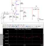
I guess C2 is the total amount of C (cable, input from JFET, etc.)?
I would be tempted to remove R5 (zero), as overload seems more unlikely now...will this affect frequency responce?
EDIT: C2 would likely not include 2sk170 input capacitance as this would be in the model?
I guess C2 is the total amount of C (cable, input from JFET, etc.)?
I would be tempted to remove R5 (zero), as overload seems more unlikely now...will this affect frequency responce?
EDIT: C2 would likely not include 2sk170 input capacitance as this would be in the model?
Last edited:
On which side of R14 does the cap go?
Good Question, I was just having the same thought when I saw your post!
Wayne does this matter, or is either end of the cap OK to place the resistor?
Russellc
I stick the cap on the ground side being a series arrangement either way should work.
hi Wayne, I did this experiment. Inserted a 220uF eletrolytic cap on the gnd side of R14. Output DC offset is indeed stable at 0 mV.
While LP is playing, i measured the DC offset is jumping around +/- 100mV. It only stayed at 0mV when Pearl 2 power is on and LP is not playing.
I did not hear any differences in term of sonic quality with and without the series capacitor so I decided to remove the cap since I think less capacitor is probably better as the sonic result.
Let me know your feedback,
Thanks,
Tom
Thank you for your guidance, it is higly regarded here
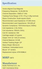
But silly me reported 400mH as inductance, but the value is 450mH...see attachment. DCR is unknown but 1kHz impedance is 2300 Ohms.
Z = 2 pi f L R
hi Wayne, I did this experiment. Inserted a 220uF eletrolytic cap on the gnd side of R14. Output DC offset is indeed stable at 0 mV.
While LP is playing, i measured the DC offset is jumping around +/- 100mV. It only stayed at 0mV when Pearl 2 power is on and LP is not playing.
I did not hear any differences in term of sonic quality with and without the series capacitor so I decided to remove the cap since I think less capacitor is probably better as the sonic result.
Let me know your feedback,
Thanks,
Tom
Others more knowledgeable than will answer, but I think that is normal. Setting power amp offset will do the same thing. You can zero it with nothing playing, but when the music starts, it begins to vary. Back to setting (or thereabouts) once it is idling.
Russellc
That sounds to me like LF resonance in the arm/cartridge, and maybe amplified record warps... If you put a scope on it you can tell for sure, or maybe do an FFT. There are a number of options if it is LF resonance or rumble, the last 2 Linear Audios have had good articles on eliminating this. See Self's articles https://linearaudio.net
I stick the cap on the ground side being a series arrangement either way should work.
Polarized with - to ground or NP?
AT150 DCR ~813Ω. You can skip the capacitor labeled C200:
Hi Jack,
Thank You once again
This is close to an experiment I am i progress with. I decided to modify an old opamp RIAA with the L/R loading. Currently using the same cartridge loading as you, but with different EQ values and also without "C200"...
The sound of this old RIAA is quite a surprice...
I stick the cap on the ground side being a series arrangement either way should work.
So it will be between R14 and R25, if I understand correctly. Is it right?
Pass DIY Addict
Joined 2000
Paid Member
Skorpio: I am curious to hear the results of your experiment with the circuit that Jack suggested! I had similar problems with an AT150MLX overloading on certain recordings. My first attempt was to reduce the gain of the second stage by adding a resistor to the Cx location. While this did reduce the overall level of output, it did nothing to remove the distortion I had. With Jack's guidance, I reduced the gain from the first stage by changing R21-R24 from 10R to 20R (closer to the Ono values of 22R) and this solved the problem for me. This reduces the gain of the first stage from ~35dB to ~30dB.
Last edited:
The sound of this old RIAA is quite a surprice...
I have an old Madison Fielding tube receiver with 12ax7's for the preamp and phono section -- it still has the nicest phono section (but the output tubes originally specified cost a fortune.) It's out of the rotation at the moment.
So it will be between R14 and R25, if I understand correctly. Is it right?
R25 Still connects to its own ground it is just shown connected to R14's ground because it was close on the schematic. Just lift the ground side of R14 and connect to the + lead of the cap and the - lead goes to ground. A bipolar cap would work here also but a standard electrolytic will work and they can take small amounts of reverse voltage but this shouldn't be a problem.
I just ordered the PCB and J-Fet to PassDIY and, while waiting, I'm thinking about my project. I read this thread, found some answers to my questions but still have some.
I was plannig to use the chipamp psu kit, but they're out of business now. So, why not use the DIYaudio universal PSU, I told myself.
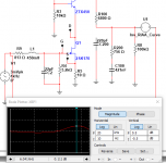
I made a little sketch:

Compared to the sketch posted by 6L6 on the first page, I change the place of the 0.22µF snubber cap after reading some discussion about it (it will be CX1 and CX2 on the PCB). Is it on the right place?
What kind of cap choose (voltage)? For example, will these be fine?
The suggested PSU use a 2*22V transformer, but they're are to find. I think I read somewhere that 2*24V will work. Right?
Will the MUR820 need heatsinks?
I put no CRC on my drawing 'cause there's no on the suggested PSU, but as the PCB offers the possibility to do it, I wonder if there'll be some benefits and, if yes, what value to use.
I think that's all (for the time being).
Thanks.
I was plannig to use the chipamp psu kit, but they're out of business now. So, why not use the DIYaudio universal PSU, I told myself.
I made a little sketch:
Compared to the sketch posted by 6L6 on the first page, I change the place of the 0.22µF snubber cap after reading some discussion about it (it will be CX1 and CX2 on the PCB). Is it on the right place?
What kind of cap choose (voltage)? For example, will these be fine?
The suggested PSU use a 2*22V transformer, but they're are to find. I think I read somewhere that 2*24V will work. Right?
Will the MUR820 need heatsinks?
I put no CRC on my drawing 'cause there's no on the suggested PSU, but as the PCB offers the possibility to do it, I wonder if there'll be some benefits and, if yes, what value to use.
I think that's all (for the time being
).Thanks.
@folkdeath95 -- the 3.3nF capacitor should be of the "X" type -- if you can't find this type use a 1kV ceramic disc. the MUR820 shouldn't need heat sinks they will only dissipate a fraction of a Watt.
220nF for the transformer snubber seems a bit much -- see Mark Johnson's thread on the "Quasi-modo jig"
Ground loop breaker -- I use them here, but our mains scheme is different from the EU.
220nF for the transformer snubber seems a bit much -- see Mark Johnson's thread on the "Quasi-modo jig"
Ground loop breaker -- I use them here, but our mains scheme is different from the EU.
- Home
- Amplifiers
- Pass Labs
- Building a Pearl 2