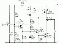
What to do when you have two large heat sinks (0.3 K/W) and a large toroid (2x18 V, 500 VA)? The answer came to me when reading Mr. Pass' article about the PLH amplifier, see http://www.passdiy.com/pdf/PLH_amplifier.pdf. Mr. Pass started with the JLH amplifier from 1969, the schematic of this amplifier is shown, at http://www.tcaas.btinternet.co.uk/jlh1969.pdf, and made his own MOSFET two stage amplifier (omitting the input transistor). So I decided to try an all-FET three stage amplifier.
Attachments
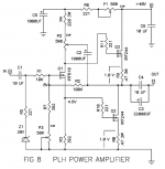
The schematic of the PLH amplifier is shown. Please observe especially the potentiometer P2, which varies the mode of operation between Single ended and Push Pull. The PLH amplifier is, as mentioned, two stage and it is inverting, and only MOSFETs are used.
Attachments
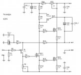
The schematic of NOStalgia is shown. I am using a plus and minus 24 V power supply, so I don't need an output capacitor. Since the input transistor is a JFET, I don't need an input capacitor either. The use of a self-biasing JFET makes it possible to avoid a current generator or a resistor (which need to be tied to a "very clean" voltage). The two last stages are very similar to the PLH amplifier with the exception of different N-channel Power MOSFETs. I am using a switch instead of a potentiometer between Single ended and Push Pull.
Attachments
How does it sound ?
I really don't know. I am finishing the testing these days. My hope is that it should sound much alike the JLH or the PLH amplifier.
I have tested the amplifier (with a rather poor) signal generator at 1 khz and 16 W output into 8 ohms using a spectrum analyzer. In the Push pull mode the second and third harmonic was down 67 dB. However this is close to the signal generator distortion, so I would not be too sure about this result. In Single ended mode the second harmonic was down 49 dB, the third down with 58 dB, the fourth down with 70 dB and the fifth down with 79 dB. Mr. Pass observed a similar difference between the Single end and Push pull mode, and was not preferring the sound from the "pure" Push pull mode. I presume the NOStalgia will have a sound similar to the PLH amplifier in this respect?
Heja Knut,
How do you expect to get 0V at the output with the FET gate tied to ground? As long as there is a current-flow through the feedback resistor R14 and a source/gate-voltage in the FET this will be impossible. But I might have missed some hidden twist") ?
?
Other FET variations is to be found in the gigantic JLH-thread. JLH is a nice topology anyway!
Since the input transistor is a JFET, I don't need an input capacitor either.
How do you expect to get 0V at the output with the FET gate tied to ground? As long as there is a current-flow through the feedback resistor R14 and a source/gate-voltage in the FET this will be impossible. But I might have missed some hidden twist
?Other FET variations is to be found in the gigantic JLH-thread. JLH is a nice topology anyway!
Thank you for your interest......As always: enough time is a problem.
JLH/PLH has been floating in my mind for some time......
Unusually I have too much time on my hands......and not enough brains
Heja Knut,
How do you expect to get 0V at the output with the FET gate tied to ground? As long as there is a current-flow through the feedback resistor R14 and a source/gate-voltage in the FET this will be impossible. But I might have missed some hidden twist
Other FET variations is to be found in the gigantic JLH-thread. JLH is a nice topology anyway!
The voltage at the source of the JFET is about minus 1.8 V when the output is at 0 V. This is enough to have a suitable current in excess of 1 mA in the P channel JFET. it works just fine.
And I agree with you about the topology.
That's very interesting amp indeed. Some DIY-ers are concern about resistors and capacitors. More advance care about transistors. But there is more in what comes out of speakers - sound characeristic i.e. harmonic distortion content. With PLH one can change from Push-Pull signal amplifing method to Single Ended, or choose and many stages between the two. (Like 2/3 AC current ratio suggested by Nelson). From this point of view it's very interesting to see in what extent sound change accordingly. That's why I think every DIY should built PLH but probably only some understand what it's about. I would like to build a one. Knut your cirquit is particulary interesting since there are no capacitors at the output, so one thing less to bother. Looking forward your final results. Thank you for PCB drawings. Pawel
Those that find this amp interesting, may also find the Amp Camp Amp #1 interesting:
http://www.diyaudio.com/forums/pass-labs/215392-amp-camp-amp-aca.html (The designer has a decent reputation)
It has some similarities:
And there is going to be a kit for it including parts (not just PCB) here at DiyAudio
http://www.diyaudio.com/forums/pass-labs/215392-amp-camp-amp-aca.html (The designer has a decent reputation
)It has some similarities:
- JFet input, though the Amp Camp Amp #1 uses the LSK170 (2SK170) which has 4 to 8 times less noise compared to J175 used in NOStalgia. LSK170 0.9-1.9 (nV/Sqr(Hz)) @ 1kHz @ 2mA(ID) vs. J175 8.0 (nV/Sqr(Hz)) @ 1kHz @ -5mA(ID). It is a little apples and oranges comparison based on the data sheet with less current (-0.2mA) the J175 noise goes up to 15. Then again now that 2SJ74 has been discontinued with no good replacement, like the LSK170 that replaces 2SK170, good p-type jfets are hard to come by. I guess if you try it and don’t hear any hiss (popcorn noise they call it in jfets, I think) it will not matter much.
- Same output devices (2x ) IRFP240.
- Depending on where you tap the output you can move between pure SE and having the top current source contribute some gain, in the Amp Camp Amp #1. And the auto bias adjust in the Amp Camp is also very nice.
And there is going to be a kit for it including parts (not just PCB) here at DiyAudio
I would have thought quite the opposite, far more to bother with, like DC offset adjustment and drift for example, and making sure voice coils don’t get fried. I can’t help thinking people make a bigger deal about having the cap. before the speaker as opposed to after it in the power supply, though I have not done subjective testing on this. Psychologically I guess it does provide less to bother with because the power supply schematic is typically drawn on a different page, so you don’t see the rail caps, just a pretty ground symbol , even though it’s still in series with the speaker, out of sight out of mind. In some cases when the cap is made too small I guess that can have an effect on base. I change my own mind on this topic all the time and can argue both sides of the fence.Knut your cirquit is particulary interesting since there are no capacitors at the output, so one thing less to bother.
- Home
- Amplifiers
- Pass Labs
- NOStalgia - the all-FET JLH/PLH Class A amplifier