...... but a delay must be imposed on the drain supply so that it comes only when the bias voltage is present.......
@ ilimzn thanks to you again for the long remarks....
")
@Salas I get my Hammonds in a week and I will try your Shunt Reg for Suburras SIT, no exotic parts besides K117GR I only have K170GR....
and is there a small delay for the drain voltage implemented, I suppose so..
@Salas I get my Hammonds in a week and I will try your Shunt Reg for Suburras SIT, no exotic parts besides K117GR I only have K170GR....
and is there a small delay for the drain voltage implemented, I suppose so..
There are points of concern especially when substituting JFETs, ask me in the Simplistic regulators thread before you start making.
There are points of concern especially when substituting JFETs, ask me in the Simplistic regulators thread before you start making.
Oh Salas, no extra work for you ....
I ordered the SK117GR!
also the reason why self-bias is recommended for those types of triodes. In triode-speak, a VFET/SIT is a low voltage, extremely high transconductance triode, so it actually falls in this category.
i drink all these words....
I started to respond to #879, then realized I have other things to do.
I hope I did not offend anyone, if so, it was not my intention.
I hope I did not offend anyone, if so, it was not my intention.
I think the smiley face meant no offense. Michael was just thinking out loud.
I hope I did not offend anyone, if so, it was not my intention.
Nah, You haven't offended me. I'm just old and weary of defending my work, so I've resolved not to. It gives me more time to build and listen to great sounding "dangerous" amplifiers.
My next amp project will be called the "Why The Hell Would You Want To Build This?".
Oh Salas, no extra work for you ....
I ordered the SK117GR!
Detail for applying the sense terminals for Marco & you. Try to keep the loop area (sense wires enclosed area) minimal. Tightly twisting their most length is welcome if feasible. Their gauge can be relatively thin. Choose that next to C1 K117GR for about 3.15mA IDSS.
Attachments
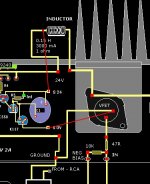
Detail for applying the sense terminals for Marco & you. Try to keep the loop area (sense wires enclosed area) minimal. Tightly twisting their most length is welcome if feasible. Their gauge can be relatively thin. Choose that next to C1 K117GR for about 3.15mA IDSS.
O.K. Salas I understood, thank you very much!
Nah, You haven't offended me. I'm just old and weary of defending my work, so I've resolved not to. It gives me more time to build and listen to great sounding "dangerous" amplifiers.
My next amp project will be called the "Why The Hell Would You Want To Build This?".
Michael, there is no intention on my part to attack your amplifier - more the other way around. I would never have given the data if I did not think of polishing the design as it evolves. Your work is in a way seminal because it shows how easy it is to implement these devices to get great sonic results, but you yourself mention how finicky the sweet spot of bias is. One possible reason is what i mentioned in that post. You have made it very clear in your article which points of the design must be adhered to for safe operation of the amp, especially heatsinking, so that the SIT is never operated close to it's maximum. This makes the design very tolerant to variations in other components and conditions which is a must for minimalistic designs, but at the same time, these variations require dialing in an 'optimum' condition which may not be permanent. My intention was to provide data to get around that for users that want to experiment and feel confident enough to do so.
The dangerous remark actually has to do with triodes - tubes are often used right at their declared maximums, especially the only ones remotely comparable to SIT voltages and currents - the ones large voltage regulator triodes found in OTL amps, and this is where the 'dangerous' experience comes from.
PS - in my experience SITs are actually remarkably robust devices. It's very easy to set-up a curve tracer so that it exposes the device under test to destructive conditions. I'm ashamed to say I did destroy a 2SJ28 that way but I would be prepared to bet that any MOSFET and not to mention BJT exposed to conditions so far outside the maximum declared values would die in miliseconds if that - it took tens of seconds for that poor 2SJ28 and it did so gracefully.
Last edited:
Hi ilimzn,
Again, you haven't offended me and I offered speedy praise for the info you've provided and I'm honestly grateful. When I see words like "dangerous" used to describe my amplifier I worry that beginners will be instanly turned-off by that sort of label. My first reaction was to respond to that with a lengthy explanation, but I decided it probably wasn't necessary. That's all really. You're most welcome in our little pub.
My terseness can be a liability sometimes.
Last edited:
you reflected so many aspects that Mike may need some time....
and ilimzn where does your intimate knowledge of V-FETs and SITs come from ....?
My first introduction to these devices came about 11 years ago, up to then I only knew about them theoretically. The initial offender was a Sony TAN5550 power amp bought on eBay for whopping $9 - you see, no-one knew what that little 'VFET' logo on the front panel meant back then. It was in rather disused shape cosmetically but worked like a charm and sounded like nothing I have heard before (and I've been listening to all sorts of amps since age 14, so that would be 29 years so far). I opened it up, looked up the output devices and... it was a good thing I was sitting down. At the time I only thought they were power JFETs, until I got hold of some other literature. In any case, I've been seeking out information and devices ever since - including lengthy discussions with J. Bongiorno and Nelson Pass back when the SIT1 was still very theoretical. As luck would have it, I had several breakthroughs in that area in the last year or so... which prompted me to get a curve tracer. So, there will be more info as I can collect and process it, in the future. In a way, it's almost like reverse-engineering datasheets, but there are still a lot of unknowns. Along the way I have experienced all save the 3 unobtainium VFET amps of the past (Sansui BA-1000, Hitachi 500F, JVC JP-M7) and owned or own and re-built most of them
which is a source for a lot of as yet unorganized data on VFET failure modes, driving circuits, pairing and paralleling issues, rank number related data etc. I have also developed and prototyped one of my own, but this is now being completely re-thought and re-designed, since new data and devices have become available to me.Hi to all!
Some new information are gathering in this fine tread - that get me thinking and wondering!! I have started my build and was soon to mount the resistors and the SK82. Now I think I was somewhat lucky - since I did buy a trafo from Antek(400watt) with 2x35 volt ac( ca2x39 volt dc) - but I got it delivered with 2x35 + 1x18 + 1x12!
So I can still use it with a choke and the 1x18(if the ampere is enough). I had my amp predesigned for selfbiasing - so that is ok! That was one of the point Ilimzn was most sceptical about? But can we use self-biasing with the Hammond-choke?
I think I will build my amp with my resistor-chain and the selfbias - with 39 volt DC - and power it up 20april(when home from sea), just to listen to the magic that Generg and everyone resistor-fans was talking about.
But I`m gonna buy a couple 2SK82 that will arrive 20april, as backup if my other devices takes to flight!! They are not that very expensive. And I think my resistor-chain is fairly stable now= 7 pieces with 400watt total = 50 watt each. So it is the same wattage as my trafo(wonder if Nelson`s SIT1 has 800watt resistor AND 800watt trafo???)
But if the high-voltage and res-chain fails - and I get me a choke - is the Anteks 18 volt AC with 2 ampere current enough to run the Hammond? Or maybe I can use zenerdiodes to lower the voltage on the 39 volt DC in 2 step(2 - 9,1 volt gives me an output =20,8 volt). Or is this solution with zeners too noisy? And is anybody running the 2SK82 with Hammond-choke AND the SelfBiasing.
Much to ponder and rethink, and do any of you gentleman have a hint? Michael, Generg, Juanitox (who is already choke-influenced)?
The road goes on - and the fun is in the prosess of discovering!!
Best to all. And thanks for inspiration to yea all!
Olav
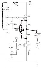
olav, first try your Sit with Res load and 1 ohm source resistor you should have 13/15V drain and 2,3 / 2,6amp ( with 40/45V supply) .
second try it with the source bypass cap ( 100000uf with 10uf MKp)
then negative bias with the 10uf Mkp at the input this time.
and last the hammond choke , you have to lowered your PS ( with a RCRC ? you have a lot of hig power resistors on hands) to 18/24V then you could try negative bias or fixed bias ( i use a 50W wirewound reosthat for that , still bypassed with 100000uf)
after all that hours of works alone , you will divorce and go fishing with friends
- Home
- Amplifiers
- Pass Labs
- L'Amp: A simple SIT Amp