Bonjour Soundhappy,
une liste, bon ben: REGA, own Millett LR Phono Preamplifier Replica (PCB datas available), own ELEKTOR battery Preamplifier (PCB datas should be available), Afken MOSFET Push/Pull, Frank Blöhbaum no R no C Amplifier Replica (PCB datas available), Volker Kluft Melomania 211 Amplifier Replica (PCB datas available), Barbara E. Gerhold AQUAVITE Replica (PCB datas available), RESO SABA Greencones Replica, B&W COTS and different from friend developped loudspeakers...
Very busy professionnaly today, I´m planning to start beginning July my own noDAC I would try it with directly coupled class A Amplifier (and a lot of other things I´ve promised such as CCS, universal SMD/THT JFET boards)
P.S.: what is the power needs of the -12V supply?
JP
what is the power needs of the -12V supply?
JP
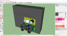
not only a study, PCB for 2SK and supplies...
JP
Hello JP
Bias supply needs are small wattage : 5 VA is a lot but if you get bigger transformer that work too.
Bridge diodes for bias supply is 2 A or more.
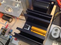
Your vfet is better on aluminium L bracked they can't be on the pcb directly because high temperature.
Your first design is great http://www.diyaudio.com/forums/pass-labs/201655-lamp-simple-sit-amp-278.html#post5089678 with huge heat sinks
")
Have a nice day
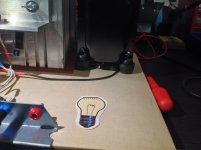
That for the future....play this morning L'Amp version with bulk foil resistors.
Have a nice sunday
I will try resistor version this week, too. Let's exchange our opinion about it.
I'm still learning this amp, which behaves very different from the other amps I have here, most probably due to high output impedance. Interaction with the woofer is very sensitive and even small bias adjustment makes measurable difference in frequency response. It is a bit like a current amp, I think. I really like the sound of this amp, so I'm trying to squeeze the best out of it. Fun time.
I will try resistor version this week, too. Let's exchange our opinion about it.
Fun time.
Yes let's exchange + 1
Few mods too this week
Attachments
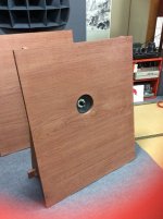
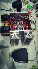
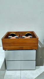
My Precious is back to live again after almost 1year dormancy, I only just wanted to separate those transformer with input rca because there was a strong hum but delayed due to OB project. testing with small speaker, no hum and no caps exploded like previous 1st turn on
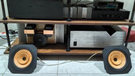
it's time to tidy up my living room, I'll have my friends visit this morning. We'll have to do some testing among SIT L'Amp vs J2 vs M2 for open baffle.
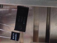
also check my drawer and found 2pair of 2SK82 and 1pair 2SJ28, if this amplifier survive another decade then my twin boys might still have a spare for replacement
it's time to tidy up my living room, I'll have my friends visit this morning. We'll have to do some testing among SIT L'Amp vs J2 vs M2 for open baffle.
also check my drawer and found 2pair of 2SK82 and 1pair 2SJ28, if this amplifier survive another decade then my twin boys might still have a spare for replacement
Attachments
also check my drawer and found 2pair of 2SK82 and 1pair 2SJ28, if this amplifier survive another decade then my twin boys might still have a spare for replacement
Helo Gadut
Well done L'Amp and you get generous heat sinks
so probably with that spare vfet's twins of your twin boys can amplify music again in all next century
Best regards
also check my drawer and found 2pair of 2SK82 and 1pair 2SJ28, if this amplifier survive another decade then my twin boys might still have a spare for replacement
Congratulations.
I think pairs of V-FETs can have better use:
Patent US4241313 - Audio power amplifier - Google Patents
After 10 years of following instructions, due to lack of formal teaching on the subject, and being totally in love with Vertical FETs, I decided to really study how amps work.
My goals are humble: repair (or mod) my new Sony TA-5650 and build power amps inspired in Yamaha B1 and Sony TA-N7, which are said to be some of the best amps out there.
The cascoded output from Sony is particularly interesting for several reasons.
Best wishes,
M.
It takes around 30minutes until heatsink temperature steady around 45°C, when its hot the vocal and treble is betterHelo Gadut
Well done L'Amp and you get generous heat sinks
so probably with that spare vfet's twins of your twin boys can amplify music again in all next century
Best regards
It's too complicated for me, dont like itCongratulations.
I think pairs of V-FETs can have better use:
Patent US4241313 - Audio power amplifier - Google Patents
After 10 years of following instructions, due to lack of formal teaching on the subject, and being totally in love with Vertical FETs, I decided to really study how amps work.
My goals are humble: repair (or mod) my new Sony TA-5650 and build power amps inspired in Yamaha B1 and Sony TA-N7, which are said to be some of the best amps out there.
The cascoded output from Sony is particularly interesting for several reasons.
Best wishes,
M.
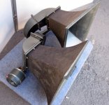
After more than 3hr listening session (no wine for sure), me and my friends agreed that SIT is the top rank amplifier and it's back on my audio rack. sadly J2 & and M2 with FW psu have to go to the corner, waiting for another purpose one day.
I also got a new 8" fullrange produced by our local expert and this is more fun to listen than alpair 10p. another speaker rolling for OB experiment will follow
is this SIT a type of current source amplifier like F2 or F2J? Since i still have some irfp metal can and 1pair R100, anyone can give a hint whether SIT could have a contender?
Attachments
Last edited:
It takes around 30minutes until heatsink temperature steady around 45°C, when its hot the vocal and treble is better
It's too complicated for me, dont like it
After more than 3hr listening session (no wine for sure), me and my friends agreed that SIT is the top rank amplifier and it's back on my audio rack. sadly J2 & and M2 with FW psu have to go to the corner, waiting for another purpose one day.
I also got a new 8" fullrange produced by our local expert and this is more fun to listen than alpair 10p. another speaker rolling for OB experiment will follow
is this SIT a type of current source amplifier like F2 or F2J? Since i still have some irfp metal can and 1pair R100, anyone can give a hint whether SIT could have a contender?
I simulated an accordion amp on VFET part 1 thread yesterday, and I noticed it has about the same output impedance as F2, 15 ohm. I thought it is useless, but it might be a good amp for full range. It's single ended, and your J2 psu can be used, so you may like it!
Last edited:
Yes let's exchange + 1
Few mods too this week
It was a bit hard to compare the resistor and choke versions directly, because the level and speaker interaction are different. I did digital EQ compensation to match their response. My choke version is more sensitive to the woofer impedance peak, resistor version is flatter. Tested at 18.5VDS, 2.0A.
Even after frequency compensation, there is a difference between them. Choke version has classic SET lush, resistor version has higher resolution. Both good, and it’s hard to choose one over the other. I tried choke and resistors at the same time. PSU - 10 ohm - choke - SIT. It has SET lush but higher resolution. I know it sounds somewhat silly, but I like it a lot. Please try this and let me know what you think.
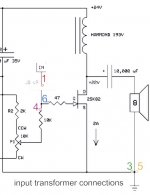
BTW, the bias circuit that I posted on 2704 is WRONG. I had to do something like post #2442. I'm not still sure if the way I’m doing is correct, but at least, the high frequency response is flat now. I wish someone would post the recommended transformer input circuit.
Last edited:
Conclusion : Mix with bulk foils resistor Vishay 10k and Mills 47R wire woud and input transformer in signal path. My TOP1

Impresed by how single 47 resistor bring changes to the sound perception
in minimalistic system with full ranges : carbons, metal film et mox.
I know is crazy to repeat few the same records and soldering desoldering resistors and try to know what is the best choice.
Spend few long evening ´s of free time and was busy in testing of my new " little " horns as well.
Haha Plasnu now you bring me into L'Amp resistor load version, CCS wait too.
Have a good time
Attachments
I know is crazy to repeat few the same records and soldering desoldering resistors and try to know what is the best choice.
hahaha, I'm cheating with alligator clips.
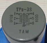
Yes 1,3 is my primary and 4,6 secondary. 5 is ground connection pin.Do you connect the 47r and 10k to the transformer like this?
bias supply---10k---transformer---47R---2sk82
Yeah i was think make with the clips toohahaha, I'm cheating with alligator clips.
but if some disconnection happen that possible danger for the vfet.
I have confidence in solid soldered connection only
Attachments
Last edited:
I wish someone would post the recommended transformer input circuit.
Transformer trick to make them be autoformer for passive extra gain stage that you mean ?
Transformer trick to make them be autoformer for passive extra gain stage that you mean ?
Not this time.
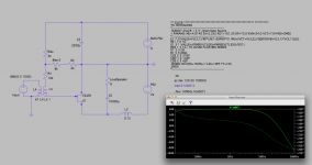
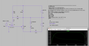
The first schematics is the simplified version of the bias scheme with 10K. It shows high frequency roll off, and I confirmed this symptom with actual amp. I changed the scheme to the second one, and the frequency plot is flatter, and I also confirmed this with actual amp.
My concern is, in the second scheme, C2 should affect the sound quality. One possible solution would be much higher bias supply voltage with 10K bias pot.
Please also check the LTSpice file attached. I may misunderstand something...
Attachments
Last edited:
Yes, it happened to me once already! Since then, I always power up the amp with Variac...but if some disconnection happen that possible danger for the vfet.
- Home
- Amplifiers
- Pass Labs
- L'Amp: A simple SIT Amp