
Yes, exactly! I recently traded out my AudioQuest Indigo speaker cable approx. 10 or 12ga for .99/ft QED 14ga (looks like white lamp cord) speaker cable and there's more bass definition with the QED. There's more to than meets the eye.
Ok, thanks for the replies.
Hi vdi_nenna
I used that cable (QED) earlier - and it was very good. Today I use it inside my speakers, where they function perfect. I also had a cheaper version of this manufacture - but the sound got rough and unpleasant(so I got rid of that one). So in my new version of Alp12P I also use the rest of it. So my Luminara and LÀmp can shine their perfect sound!
Best
Olav
A couple of really swell guys have sent me a few 2SK182ES,
so I have some good ones now and I can give them some more serious attention.
Thanks for great Diyers and Michael that is fantastic


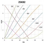
I have found a 1Henry 1A Choke that id like to use as an inductor for this amp. With the restriction of 1A current can someone help me establish an ideal operating point and the approx. output power in watts this point would produce. I just don't know how to work out the output power and gain i could get from the 2sk82 curves.
Last edited:
You can measure the voltage across inductor if you are sure about coil dcr. If coil warms dcr will change a little, but not much to worry unless coil wire gauge is small.
Is possible to add some resistor in series with the inductor to measure the bias current. The resistor will lose some little +B, but will help somewhat with filtering. I used a 0R2/10W in my supply.
Is possible to add some resistor in series with the inductor to measure the bias current. The resistor will lose some little +B, but will help somewhat with filtering. I used a 0R2/10W in my supply.
I have found a 1Henry 1A Choke that id like to use as an inductor for this amp. With the restriction of 1A current can someone help me establish an ideal operating point and the approx. output power in watts this point would produce. I just don't know how to work out the output power and gain i could get from the 2sk82 curves.
Max unclipped power due to inductor current is 0.5*(I^2)*R, so for 8 ohms you'd get only to 4 Watts max.
Max unclipped power due to inductor current is 0.5*(I^2)*R, so for 8 ohms you'd get only to 4 Watts max.
Thank You for helping me. I now understand the power calculation a bit better
Can you tell what is the .5 figure please.
Power = I(rms)^2 * R, I(rms) = I(peak)/sqrt(2)
Hence Power = 0.5 * I(peak)^2 * R.
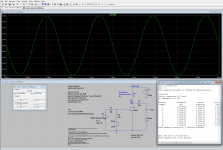
Take note that with a real 2SK82 curve and Id constraint of 1A, THD will go to the roof for power approaching 4W. I did a quick SPICE simulation, with 1A THD is around 2-3% at 1W, and around 10% approaching 4W.
Hence Power = 0.5 * I(peak)^2 * R.
Take note that with a real 2SK82 curve and Id constraint of 1A, THD will go to the roof for power approaching 4W. I did a quick SPICE simulation, with 1A THD is around 2-3% at 1W, and around 10% approaching 4W.
Power = I(rms)^2 * R, I(rms) = I(peak)/sqrt(2)
Hence Power = 0.5 * I(peak)^2 * R.
Take note that with a real 2SK82 curve and Id constraint of 1A, THD will go to the roof for power approaching 4W. I did a quick SPICE simulation, with 1A THD is around 2-3% at 1W, and around 10% approaching 4W.
Geez Thats not so good, Was the spice model if i set the device at this operaing point , Mine is the dashed loadline
Attachments
Geez Thats not so good, Was the spice model if i set the device at this operaing point , Mine is the dashed loadline
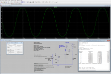
The model I used was downloaded from audiohobby.com, I set the condition closer to the operating point you chose (still not the same, as the model seems different from the curve you showed), and it performs better:
0.2W 0.26%
1.0W 1.37%
3.8W 8.38%
Attached the screenshot and the .asc file I used for the simulations.
Attachments
Observing the characteristic curves of a typical SIT clearly one noticed that it needs a specific load to lower/good use THD (load-line cancellation). Loads larger or smaller increase THD, contrary to the triodes, which always reduce THD when we relieve the load. I had proven this in practice with FFT measurements in 2012 when I bought my first SIT's.
This means if we diverge much from the operating point typically used in projects here, THD will rise. Or also using lighter loads, such as headphones, the THD and the harmonic spectrum changes, but since headphones are quite sensitive in general, so the THD increase likely would be more than compensated by the 'phones sensitivity. This partially answers the Dzius question, but the biggest question for use in headphones would make the power supply with the lowest possible ripple in order to not get noisy audio with the use of headphones. And use an smaller cap for output coupling for not destroying phones at startup.
This means if we diverge much from the operating point typically used in projects here, THD will rise. Or also using lighter loads, such as headphones, the THD and the harmonic spectrum changes, but since headphones are quite sensitive in general, so the THD increase likely would be more than compensated by the 'phones sensitivity. This partially answers the Dzius question, but the biggest question for use in headphones would make the power supply with the lowest possible ripple in order to not get noisy audio with the use of headphones. And use an smaller cap for output coupling for not destroying phones at startup.
Do you mean SIT=Vfet?
In this case, Vfet, have the same curves of triodes. Ergo, More signal more distortion.
The transference curve between G and D is like triode. If you trace the load line and work with this, Static or dynamic they are the same like triodes, they have µ like triodes.
In this case, Vfet, have the same curves of triodes. Ergo, More signal more distortion.
The transference curve between G and D is like triode. If you trace the load line and work with this, Static or dynamic they are the same like triodes, they have µ like triodes.
Do you mean SIT=Vfet?
In this case, Vfet, have the same curves of triodes. Ergo, More signal more distortion.
The transference curve between G and D is like triode. If you trace the load line and work with this, Static or dynamic they are the same like triodes, they have µ like triodes.
") Sure, but lacks one detail: if you pay close attention, the curves of a VFET and most SIT's are closer to each other when Vg approaches zero (bunching). That is, the device has rp and μ triodes done, but they are "bunching" also close to 0V, and the cutting region is relatively OK, while the triodes are more bunching near cutoff and clean to g=0V. Try to measure the THD of a SIT / VFET when operating without load and using current source or high quality inductor in the drain, and it will be clear what I'm saying (or use an good simulator). Triodes will be only low 2H without load, and SIT will be high THD, specially 2H. The VFET graph clearly reveals this. This means that an SIT / VFET has an inverted triode style. See the result of a "inverted triode" called SuperTriode at this link:
Sure, but lacks one detail: if you pay close attention, the curves of a VFET and most SIT's are closer to each other when Vg approaches zero (bunching). That is, the device has rp and μ triodes done, but they are "bunching" also close to 0V, and the cutting region is relatively OK, while the triodes are more bunching near cutoff and clean to g=0V. Try to measure the THD of a SIT / VFET when operating without load and using current source or high quality inductor in the drain, and it will be clear what I'm saying (or use an good simulator). Triodes will be only low 2H without load, and SIT will be high THD, specially 2H. The VFET graph clearly reveals this. This means that an SIT / VFET has an inverted triode style. See the result of a "inverted triode" called SuperTriode at this link:Report page Note how the curves of the graph is similar to the SIT / VFET!
I see people in the Net praising the Super Triode sound and we like the SIT/VFET sound, so this "inverted bunching" is not an defect here! But this is an clear fact and I like to know the truth.
Meu amigo, There are triodes and triodes, there are triodes with enhancent behaviour and need positive value on the grid, there are triodes that bounch near of 0 volt, high mu triodes bounch like that, and there are Vfet that not bounch at all.
If you put a ccs you horizontalize the load line but you can make the same with both devices, take the 2sK79, if you compare it with a ECC88, they are close the same, Vfet have less Rp(Rd) but by cassuality recently we took curve trace without this Bounching closing to 0. I don't know which data did feed your simulator.
If you put a ccs you horizontalize the load line but you can make the same with both devices, take the 2sK79, if you compare it with a ECC88, they are close the same, Vfet have less Rp(Rd) but by cassuality recently we took curve trace without this Bounching closing to 0. I don't know which data did feed your simulator.
- Home
- Amplifiers
- Pass Labs
- L'Amp: A simple SIT Amp