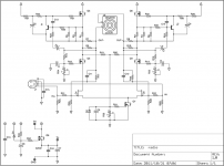
I have been working on a schematic for an amplifier that I would like to build, and I've decided to solicit comments here. Since I plan on making a minimum run of boards for my first build, I thought it might be prudent to ask for suggestions and perhaps even find some folks who'll want the inevitable extra boards. Please bear with me while I try to cover everything in this introductory posting, but feel free to ask questions or make suggestions.
BACKGROUND:
I have a nice DAC with balanced outputs capable of +26 dBu at about 50 Ω. This makes me believe that I do not need to design a preamp. I prefer the Super Symmetric amplifier design with balanced inputs and floating speaker outputs. It also seems like a good idea to start with the latest Zen Variation (#9), although I do not really know whether the JFET input is absolutely needed.
GENERAL GOALS:
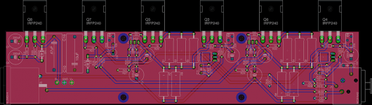
I hope to design the PCB with multisite options for various contingencies that I might run into. Personally, I don't want to mess around with breadboarding or point-to-point wiring, and since multiple fab houses are available nearby in my city I figured I might as well start with a custom PCB. The idea is to put every extra resistor, pot, capacitor size variation, regulation, and anything else that I might anticipate on the board, so long as these extra parts can be left out and still have a functional board.
COMPATIBILITY:
I do not see many people talking about the new standard PCB sizes and mounting holes for PCB and transistors, but it seems like a good idea to follow these. I downloaded the PDF from the store and designed by PCB to fit. I do not have heat sinks or a case, yet, but hopefully it will be much easier to find a standard one.
UNIQUE CHOICES:
I put a Neutrik PCB-mount XLR balanced input, and a Neutrik PCB-mount speakON output directly on the board. This means I'll need to make a mirror image of my board if I want to build Left and Right into the same enclosure with inputs on the front and outputs on the back, with heat sinks on the left and right. I realize that this is probably a rather odd choice, but point-to-point wiring from panel mount jacks can just as easily be soldered to the PCB-mount pads if you don't like this arrangement. The Neutrik powerCON was not available in a PCB-mount package, so the board accepts soldered power inputs, regulated or unregulated.
OTHER NOTES:
I have no idea where to find the LU1014D parts, but I've designed for the surface-mount heat sink. I have a hunch the layout may need to be modified to allow more heat sinking for the JFET input transistors.
R0A-R0D are optional.
Those of you who don't like feedback can leave out the appropriate parts, but SuSy won't work without at least certain feedback.
I tried to think of anywhere that more variable resistors might prove useful, even if they're only mounted on the board long enough to experiment before replacing with precision resistors. Any suggestions here would be particularly appreciated.
I still feel like I have more reviewing and tweaking to do, but the schematic has settled for a while now so it seems ready for comment. Please let me know if I've made any obvious beginner mistakes! (but please also comment if you have anything to offer)
BACKGROUND:
I have a nice DAC with balanced outputs capable of +26 dBu at about 50 Ω. This makes me believe that I do not need to design a preamp. I prefer the Super Symmetric amplifier design with balanced inputs and floating speaker outputs. It also seems like a good idea to start with the latest Zen Variation (#9), although I do not really know whether the JFET input is absolutely needed.
GENERAL GOALS:
I hope to design the PCB with multisite options for various contingencies that I might run into. Personally, I don't want to mess around with breadboarding or point-to-point wiring, and since multiple fab houses are available nearby in my city I figured I might as well start with a custom PCB. The idea is to put every extra resistor, pot, capacitor size variation, regulation, and anything else that I might anticipate on the board, so long as these extra parts can be left out and still have a functional board.
COMPATIBILITY:
I do not see many people talking about the new standard PCB sizes and mounting holes for PCB and transistors, but it seems like a good idea to follow these. I downloaded the PDF from the store and designed by PCB to fit. I do not have heat sinks or a case, yet, but hopefully it will be much easier to find a standard one.
UNIQUE CHOICES:
I put a Neutrik PCB-mount XLR balanced input, and a Neutrik PCB-mount speakON output directly on the board. This means I'll need to make a mirror image of my board if I want to build Left and Right into the same enclosure with inputs on the front and outputs on the back, with heat sinks on the left and right. I realize that this is probably a rather odd choice, but point-to-point wiring from panel mount jacks can just as easily be soldered to the PCB-mount pads if you don't like this arrangement. The Neutrik powerCON was not available in a PCB-mount package, so the board accepts soldered power inputs, regulated or unregulated.
OTHER NOTES:
I have no idea where to find the LU1014D parts, but I've designed for the surface-mount heat sink. I have a hunch the layout may need to be modified to allow more heat sinking for the JFET input transistors.
R0A-R0D are optional.
Those of you who don't like feedback can leave out the appropriate parts, but SuSy won't work without at least certain feedback.
I tried to think of anywhere that more variable resistors might prove useful, even if they're only mounted on the board long enough to experiment before replacing with precision resistors. Any suggestions here would be particularly appreciated.
I still feel like I have more reviewing and tweaking to do, but the schematic has settled for a while now so it seems ready for comment. Please let me know if I've made any obvious beginner mistakes! (but please also comment if you have anything to offer)
Attachments
Just for an additional note , I have built a sort of ZV8 - like circuit , with the IXTH depletion Mosfet that sounds promising . Of course the curve of the LU1014D is quite different ( and the biasing ) compared to Dmosfet .OTHER NOTES:
I have no idea where to find the LU1014D parts, but I've designed for the surface-mount heat sink. I have a hunch the layout may need to be modified to allow more heat sinking for the JFET input transistors.
Still have some LU1014D around , but I am afraid will not be able to mach 4 of them for this design .
Thanks
Stefano .
Thanks for the comments.
Besides, what's wrong with DC coupling? My present DAC has output caps, but I plan on upgrading to a DC-coupled DAC when funding allows.
I must admit that I do not know how ZV8/9 expect to keep the Vgs around the ideal -1 V (besides, the JFET input is not necessarily required). Now that you have me thinking about it, I wonder how much padding I will need on the +26 dBu DAC outputs, and therefore how much extra gain I'll need in this little amp.
Why? ZV8 & ZV9 don't have input caps.you'll need input caps
Besides, what's wrong with DC coupling? My present DAC has output caps, but I plan on upgrading to a DC-coupled DAC when funding allows.
I must admit that I do not know how ZV8/9 expect to keep the Vgs around the ideal -1 V (besides, the JFET input is not necessarily required). Now that you have me thinking about it, I wonder how much padding I will need on the +26 dBu DAC outputs, and therefore how much extra gain I'll need in this little amp.
Q7 is an active current source from ZV7, and I believe it replaces the source resistors in similar designs. Again, however, I'll admit that I'm just cutting and pasting here. Are the Lovoltech JFETs different than the typical FETs in ZV7 with regard to degeneration/load-line shaping?besides that - you'll need some source resistors for LU critters - degeneration-load line shaping purpose
Looking at ZV8, it mentions that the ideal input bias for Vgs is -1 V. This makes me hypothesize that ZV8 might be best for low-level signals around +4 dBu. What will happen when I send +/-8 V (+24 dBu)?I have built a sort of ZV8 - like circuit , with the IXTH depletion Mosfet that sounds promising . Of course the curve of the LU1014D is quite different ( and the biasing ) compared to Dmosfet .
In other words, maybe I should alter the input transistor to handle my specific DAC output. I can pad the DAC output, but I imagine that I might turn it up to full +24 dBu with possibly even +26 dBu peaks.
Thanks for the comments.
Why? ZV8 & ZV9 don't have input caps.....
yes , but they don't have CCS below , and that critter ( CCS) needs some voltage to not be dead as Dodo
I told you - search for Donut amps ; everything ( and then some ) is drawn there
edit: here it is , just for your amusement :
http://www.diyaudio.com/forums/pass-labs/133433-choky-susy-f3-lu1014s.html
Attachments

Last edited:
I remember reading that thread. Choky ain't SuSy. It needs the shorted tails like in all of the SuSy articles. Like Babowana says. It doesn't make sense to me to think of the source resistors as integral to the LUs, otherwise Papa never would have removed them to make SuSy. Wouldn't it be possible to think of the source resistors as part of the original Zen FETs? I don't think so, in either case.I told you - search for Donut amps ; everything ( and then some ) is drawn there
edit: here it is , just for your amusement :
http://www.diyaudio.com/forums/pass-labs/133433-choky-susy-f3-lu1014s.html
Besides, Nelson Pass never commented on Choky to say that it implements his patented Super Symmetric design. We should all re-read the patent!
Admittedly, Choky may sound great, but that doesn't mean it's SuSy. Also, my Frankenstein above at the start of this thread may not work for many reasons, but that's not really related to whether Choky is SuSy.
The active current source is biased by R19 & R20, and adjusted by R36. I would hope that it has some voltage! The articles mention the minimum bias.yes , but they don't have CCS below , and that critter ( CCS) needs some voltage to not be dead as Dodo
However, are you saying that the Vgs of the Lovoltechs needs to be different because of the source biasing? I must admit that I don't understand the JFET gate biasing at all in the ZV8/9 articles...
feel free to re-read the Patent 
those Donut amps are SUSY .
not splitting the hair or arguing , that's just fact .
regarding Jfets - you need to learn their biasing methodes , voltages , then you'll see what you need to change
every part need proper operating voltages
those Donut amps are SUSY .
not splitting the hair or arguing , that's just fact .
regarding Jfets - you need to learn their biasing methodes , voltages , then you'll see what you need to change
every part need proper operating voltages
Last edited:
Says who? The Court Jester? Papa?feel free to re-read the Patent
those Donut amps are SUSY .
not splitting the hair or arguing , that's just fact .
Has anyone introduced a spike into one half of the Donut and watched it appear inverted on the other side? If so, it is happening via the transformer or via the tail?
well - I have no intention to give you certificate on inspection
if you have doubts - check by your self .
besides these things - Choky isn't name of the concept ( but one day I might use it for some ) ;
Choky is my (previous) nick , same as Zen Mod .
I'm off now - because you got it wrong - I don't care are you going to build Halcro , or my schm , or your schm ; all I said is that you need caps on input and slight rearranging of Jfets biasing resistors , to let them and CCS breath .
if you have doubts - check by your self .
besides these things - Choky isn't name of the concept ( but one day I might use it for some
) ;Choky is my (previous) nick , same as Zen Mod .
I'm off now - because you got it wrong - I don't care are you going to build Halcro , or my schm , or your schm ; all I said is that you need caps on input and slight rearranging of Jfets biasing resistors , to let them and CCS breath .
I would defer to ZM on this one. He is salty dog on Mr Pass' black arts.
Why would active current source be any different with or without Rs. Need only share CS to share error correction. Resistor just object in chain for degeneration. Understanding Choky SUSY vs ZV6 is more about mosfet vs JFET than anything.
Why would active current source be any different with or without Rs. Need only share CS to share error correction. Resistor just object in chain for degeneration. Understanding Choky SUSY vs ZV6 is more about mosfet vs JFET than anything.
Last edited:
I didn't say the current source would be different, I said that the symmetry would not be super. There are many active current sources in the collection of Zen Variations articles. I'm not even saying that I biased the active current source (Q7) correctly, so I certainly wouldn't be complaining about suggestions there.Why would active current source be any different with or without Rs.
ZV6 has no current source - or at least no active current source. The operative phrasing in that article is that the two halves of the amplifier must share the error current - that doesn't seem equivalent to saying that they must share a current source. Seems to me that a couple of degeneration resistors would convert the error current to voltages and prevent sharing an identical error current on both sides. I could easily be missing something, of course.Need only share CS to share error correction.
I'm just curious why the degeneration was removed in ZV6. The ZV6 article starts with the Son of Zen, then removes the individual biasing resistors so that the error current flows directly from one transistor to the other.Resistor just object in chain for degeneration.
Maybe I should review the finer points of degeneration, and whether the term is necessarily distinct from a source biasing resistor.
Also, if there is a convincing case made for the Choky Donut being SuSy, then I haven't seen it. The thread that was linked started out saying it might be, then saying that only Papa could say, and then when Papa said nothing in the entire thread it seems that folks just assumed that was some kind of stamp of approval. More than one person pointed out that the Donut was not SuSy, and not a single supporting rebuttal was made. I'm here to learn things, not just assume that something is true because someone says it's a fact. If the argument has already been presented elsewhere, then I'll try my best to catch up - just provide a link.
well - I really don't care ....
but - with that sort of attitude you'll probably miss grasping some knowledge here and there , from much more knowledgeable ppl , than you and me .
I'm still greenhorn here , but you're obviously even greener
SUSY is/was least important thing in Donut amps ; what's more important is cause why they're sketched , why/how Magura's amp was made and why ppl were having fun in those few threads
who cares about SUSY ..... especially when one knows how it's made
Attachments
Look for variations of Jfet BOSOZ. THere is a lot of good info in those threads but the like of GRollins, MAgura, ZM, and couple of other fellows who know SUSY not from theory but raw immersion in mistakes and revelations. Some of the iterations use CS and some use other means, but all have pretty good explanations.
Hi rsdio !
The way I see it:
Susy: the idea is, to feed the distortion from one leg (arm?) to the other, so it will apear as a common mode signal at the output (and cancel). If there is a current source at the tail there will be no common signal at the output, as the current is constant. So no Susy. With crossfeed we might call it Susy, but the cancelation will happen at the input not the output.
Source resistors: If you want loadline cancelation as described by mr. Pass, you need some voltage swing over the FETs. If you dont want source resistors you can place the resistors at the drains, between the FET and MOSFET ( 0,1 to 1 ohm ).
Caps: If you dont want DC at the inputs, you have to put a cap in the feedback path or at the input.
Thorsten Larsen
Hi rsdio !
The way I see it:
Susy: the idea is, to feed the distortion from one leg (arm?) to the other, so it will apear as a common mode signal at the output (and cancel). If there is a current source at the tail there will be no common signal at the output, as the current is constant. So no Susy. With crossfeed we might call it Susy, but the cancelation will happen at the input not the output.
Source resistors: If you want loadline cancelation as described by mr. Pass, you need some voltage swing over the FETs. If you dont want source resistors you can place the resistors at the drains, between the FET and MOSFET ( 0,1 to 1 ohm ).
Caps: If you dont want DC at the inputs, you have to put a cap in the feedback path or at the input.
Thorsten Larsen
How do the ALeph X amps work with CCS on the tail?

Hi Buzz !
I just speak from my own understanding. I believe that the test of Susy is, that there is less distortion between the two outputs than from one output to ground. That means that there has to be a common signal at the outputs. I cant see that happening with a current source at the tail. Im not familiar with the Aleph X. Does it have crossfeed?
Im willing to learn.
Thorsten Larsen
Aleph X is - for instance - plain Aleph 30 , with output stage multiplied to left side , with modulation of it taken from (till then) unused LTP's drain
feedback net is then slightly revised , so each side is -sort of - working in inverted mode
there are myriad of threads floating in Papaland , but if you search and chose oldest one , you'll grasp some crumbs .
and yes - Tail there is Archimedes's Rest , for SUSY
feedback net is then slightly revised , so each side is -sort of - working in inverted mode
there are myriad of threads floating in Papaland , but if you search and chose oldest one , you'll grasp some crumbs .
and yes - Tail there is Archimedes's Rest , for SUSY
- Status
- This old topic is closed. If you want to reopen this topic, contact a moderator using the "Report Post" button.
- Home
- Amplifiers
- Pass Labs
- ZV9X : A JFET input ZV7