You, hello.
I am a Japanese, sorry for poor English.
I am using STASIS2 for about 30 years. It is very pleasing.
I made the mistake by being careless during maintenance work.
While measuring the voltage of the Left ch. power transistor, the pin of the power transistor
was made to be touched with a tester's probe, and short-circuit was caused.
The resistance (300 ohm) on PRE-STAGE Board burned violently.
Left ch. received the severe damage.
The transistor and resistance which received the damage were exchanged.
(Details, please see attached file.)
But, power is turned ON, it will be in the following states.
- a loud ham(AC) noise sound comes out.
- The indicator of an ammeter in -Rail swings past the maximum.
- A -Rail fuse goes out immediately.
POWER-STAGE of Left ch. is recovered.
This is confirmed using PRE-STAGE Board of Right ch. (No Damage).
It seems that there is a problem in PRE-STAGE Board of left ch.
Since it is in such a state, it cannot connect with POWER-STAGE again and cannot test.
Then, I want you to teach.
Is there any person who separated from POWER-STAGE and tested only PRE-STAGE Board?
I would like to check the voltage of the key point of Left ch. PRE-STAGE Board.
I compare the voltage of Left ch. PRE-STAGE Board and Right ch. (No Damage).
For that purpose.
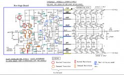
(The following colors, please see wiring of an attached file.)
- It understands that the power supply of +/- 75V is required for yellow.
I can make the independent small power supply for a test.
- Is black OK without load?
- Does gray require +/- 45V?
If required, how ohm resistance should be connected to +/- 75V about?
- Is blue OK without load?
About how to advance a test
- Is it better to connect and test 75V from the start?
- Is it better to test from low voltage (for example, 9V->40V->75V)?
In addition, if there is a good method, please let me know.
Thank you.
I am a Japanese, sorry for poor English.
I am using STASIS2 for about 30 years. It is very pleasing.
I made the mistake by being careless during maintenance work.
While measuring the voltage of the Left ch. power transistor, the pin of the power transistor
was made to be touched with a tester's probe, and short-circuit was caused.
The resistance (300 ohm) on PRE-STAGE Board burned violently.
Left ch. received the severe damage.
The transistor and resistance which received the damage were exchanged.
(Details, please see attached file.)
But, power is turned ON, it will be in the following states.
- a loud ham(AC) noise sound comes out.
- The indicator of an ammeter in -Rail swings past the maximum.
- A -Rail fuse goes out immediately.
POWER-STAGE of Left ch. is recovered.
This is confirmed using PRE-STAGE Board of Right ch. (No Damage).
It seems that there is a problem in PRE-STAGE Board of left ch.
Since it is in such a state, it cannot connect with POWER-STAGE again and cannot test.
Then, I want you to teach.
Is there any person who separated from POWER-STAGE and tested only PRE-STAGE Board?
I would like to check the voltage of the key point of Left ch. PRE-STAGE Board.
I compare the voltage of Left ch. PRE-STAGE Board and Right ch. (No Damage).
For that purpose.
(The following colors, please see wiring of an attached file.)
- It understands that the power supply of +/- 75V is required for yellow.
I can make the independent small power supply for a test.
- Is black OK without load?
- Does gray require +/- 45V?
If required, how ohm resistance should be connected to +/- 75V about?
- Is blue OK without load?
About how to advance a test
- Is it better to connect and test 75V from the start?
- Is it better to test from low voltage (for example, 9V->40V->75V)?
In addition, if there is a good method, please let me know.
Thank you.
Attachments
first - de-solder each transistor from pcb - one at a time , and check with diode test .
if bad - replace , if good , solder it back .
when finished , you can check operation of front end without output stage .
power it up , put sine wave on input and observe amplified sine wave on Tr12 or Tr13 base , referenced to gnd
if you follow that ( checking each transistor ) procedure , along with measuring suspicious resistors , you can freely power up front end pcb connected normally on amplifier's PSU
or - you can put temporary 100mA fuses in all PSU lines ; you'll need 6 of them
Last edited:
Thank you for the quick advice Mr. Zen Mod.
All of a transistor and a diode were checked.
Transistor.
- It is checked whether the emitter to collector shorted or not.
- When not shorted, it checks that contact collector and base with a finger
and the deflection condition of a tester's indicator does not differ from
a normal transistor greatly.
Diode.
- It checks that there is no condution reverse polarity.
However, because of a check with an analog tester, normal in the situation of high voltage or it cannot judge in abnormalities.
Then, I am making the plan.
1. Make the small power supply for a test.
2. Check whether sign wave is amplified correctly(Between base and ground of TR12
and TR13), applying voltage to a yellow line gradually.
3. At first, don't give voltage to a gray line.
I try.
Since there is no oscilloscope, it checks hearing sound.
Thank you.
- Status
- This old topic is closed. If you want to reopen this topic, contact a moderator using the "Report Post" button.