M-Audio vs HP 8903B
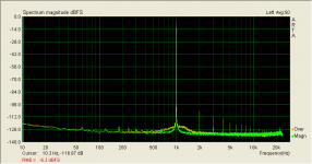
Here is a little test of my M-Audio Fast-Track Pro USB soundcard vs an HP 8903B distortion analyzer. In the plot below, the green is the M-Audio looped back into itself and the orange trace is the signal from the HP. The M-Audio looks just slightly cleaner.
The 8903B does detect some HF noise coming out of the M-Audio, about 3mV worth. I'll have to check that on the o'scope. If I use the 80Khz low pass filter on the HP, then the THD+N results approximately agree between it and what the computer tells me.
It a nice look at an inexpensive way to measure. Running at 96Khz sampling rate is similar. The advatage of the HP is that it measures up to 100Khz, but the M-Audio and computer show you the actual harmonics and noise floor
Attachments
The high frequency noise from the M-Audio board is due to the dither and noise shaping of the DAC. The biggest drawback of the M-Audio board is the limited number of harmonics of 20kHz that can be measured. OTOH, CCIF and SMTPE tests can be used to measure high frequency distortion products without the need for higher sampling rates.
Yep, would like to be able to see out to 100Khz, but that's not happening with this card. Some of the M-Audio cards can see up to about 80Khz when using the 192Khz sampling rate.
The noise may well be dither, or something else. It's there whether there is a tone running or not. The HP says:
3.3mV full bandwidth
0.33mV 80Khz BW
0.027mV 30Khz BW
0.0095mV A weighted 80Khz BW
The noise may well be dither, or something else. It's there whether there is a tone running or not. The HP says:
3.3mV full bandwidth
0.33mV 80Khz BW
0.027mV 30Khz BW
0.0095mV A weighted 80Khz BW
I'm looking for a good soundcard for $120. I was looking at the Xonar D1. I need something with at least 110db SNR and 192KHz samplerate. My current soundcard is an on-board STAC9227 which actually is not too bad, except for very noisy output.
Are there any new soundcards on the market in this range? The Creative SBX sounds interesting, but Creative does not have a good track record...
I suppose I could keep buying cards and returning them until I found something suitable? Whatever it is needs to be compatible with Linux.
Where can I find measurements of the cards in question?
I have been happy with the M-Audio Audiophile-192. It is available for around $100 and it works well with Linux.
I'm looking for a good soundcard for $120. I was looking at the Xonar D1. I need something with at least 110db SNR and 192KHz samplerate. My current soundcard is an on-board STAC9227 which actually is not too bad, except for very noisy output.
Are there any new soundcards on the market in this range? The Creative SBX sounds interesting, but Creative does not have a good track record...
I suppose I could keep buying cards and returning them until I found something suitable? Whatever it is needs to be compatible with Linux.
Where can I find measurements of the cards in question?
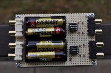
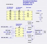
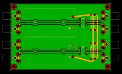
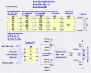
I recently zapped my M-Audio Audiophile-192 due to an accidental short circuit while testing a preamplifier card. I decided it was time to build an interface with over voltage protection. AA batteries and diodes limit the range of the soundcard input and inputs and outputs to about +/- 3.6V. Eight-pin dip plugs with resistors provide current limiting and customizable attenuators. Loopback measurements look fine. Here it is:
Attachments
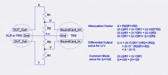
I'm not sure how the circuit works with a balanced circuit, as a balanced circuit has no direct reference to ground. The XLR connector pin #1 is chassis not circuit ground.
I have found that most consumer balanced audio has pin 1 connected to signal ground rather than chassis ground. Whether pin 1 is connected to signal ground or chassis ground, the attenuators shown will work correctly. Any issues with the ground will be common mode.
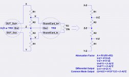
However, balanced attenuators are normally built as shown in the following schematic. (Note that the voltages to the clamp diodes are reversed from the previous drawing which was incorrect). When I compared the noise levels using these balanced attenuators vs. the grounded attenuators shown in the previous post, I found slightly lower noise levels in the grounded attenuators. This is with the signal source being an M-Audio Audiophile-192 soundcard.
Attachments
I presented a soundcard interface that can be used for either balanced or unbalanced sources and sinks. The attenuators were primarily designed to match the voltage swing from an amplifier output to the permissible voltage swing of the soundcard input. There is no intent for these attenuators to be used for more general balanced audio interconnection.
Here is a simple analysis of the grounded attenuator in post #28 http://www.diyaudio.com/forums/pass...ier-distortion-measurement-3.html#post3706107, " and the ungrounded attenuator in post #31 http://www.diyaudio.com/forums/pass...ier-distortion-measurement-4.html#post3735528. The major difference is in the common mode output. The grounded attenuator reduces the common mode by the same factor as the difference signal whereas the ungrounded attenuator retains the full common mode level.
Here is a simple analysis of the grounded attenuator in post #28 http://www.diyaudio.com/forums/pass...ier-distortion-measurement-3.html#post3706107, " and the ungrounded attenuator in post #31 http://www.diyaudio.com/forums/pass...ier-distortion-measurement-4.html#post3735528. The major difference is in the common mode output. The grounded attenuator reduces the common mode by the same factor as the difference signal whereas the ungrounded attenuator retains the full common mode level.
Attachments
Post #31 shows an alternative without batteries. I chose batteries so that additional power supplies were not required. It might work fine with just the Zeners and switching diodes and no extra bias current, but I have not measured the distortion created by leaving the Zeners unbiased. What I would expect is that the Zeners will charge to the levels defined by the min and max peaks of the signals.Will the clamping diodes only work with batteries ?
Best regards
Arthur.
")
- Status
- This old topic is closed. If you want to reopen this topic, contact a moderator using the "Report Post" button.
- Home
- Amplifiers
- Pass Labs
- Balanced Soundcard Interface for Power Amplifier Distortion Measurement