hey all,
let me start by thanking Petter, on whose work i built.
 Nelson Pass once stated in the old X100 backengieneered thread that the X1000 uses cascoded input devices "to keep the power dissipation down"..
Ok.
But i think the true reason is that you need the additional cascode to be able to truly make an X circuit. The distinguishing feature, from my point of view, is that you take feedback "from the other side". When you have only the folded cascode, as in Petters and Uli's amps, you have to feed back from the same side - so in my view these are not X amps - where's the X?
(the Aleph X has it, no need to get excited)
the "magic" resistor that couples the diff amps tails has nothing to do with it, it is just a current feedback mechanism - it is not new or anything, it's in my circuit design book actually...
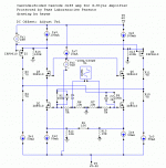
Please take a look at the attached schematic.
there are a few extra resistors to make the sim converge..(R12-R15) + comp. caps 1pF each.
the X is below the source, in the middle...
I'm looking forward to your comments.
Regards,
keyne
let me start by thanking Petter, on whose work i built.
Nelson Pass once stated in the old X100 backengieneered thread that the X1000 uses cascoded input devices "to keep the power dissipation down".. Ok.
But i think the true reason is that you need the additional cascode to be able to truly make an X circuit. The distinguishing feature, from my point of view, is that you take feedback "from the other side". When you have only the folded cascode, as in Petters and Uli's amps, you have to feed back from the same side - so in my view these are not X amps - where's the X?
(the Aleph X has it, no need to get excited)
the "magic" resistor that couples the diff amps tails has nothing to do with it, it is just a current feedback mechanism - it is not new or anything, it's in my circuit design book actually...
Please take a look at the attached schematic.
there are a few extra resistors to make the sim converge..(R12-R15) + comp. caps 1pF each.
the X is below the source, in the middle...
I'm looking forward to your comments.
Regards,
keyne
Attachments
Depending on the polarity of the amplification which follows
the differential input pair, you take the feedback from either side.
Odd numbers of Comon-Source gain stages (including the diff
pair as a gain stage) use the same side, and on even they
use the opposite side for the source of feedback.
The X circuit does not require cascoding, but certainly can be
made to benefit from it, just like any other amplifier.
Hi Keyne
I don't think I agree, not yet atleast ...
The Q5 and Q6 do nothing for the polarity of the voltage or current signal involved., so I don't see how they can make a difference for the feedback 'take-off points' ...
The upper nodes of Q2 and Q3 don't feature (much) voltage swing .. they are allready cascoded, allthough with a folded cascode....so a additional cascode would not make much of a difference for linearity or bandwith...
I think the additional cascodes Q5 and Q6 serve to spread the dissipation ... putting less heat stress on each of the MOSFETS..
I'll try some simmulations my self.... let's hear it from the others..
Regards,
Thijs
Mr Pass,
thanks for your comment, i see my error now!
I've been fooled by my simulation...


Mr. Pass, so the distinguishing feature is not the "X" in the schematic, but the distortion cancellation mechanism at work, right?
Thijs, your points are correct.
I still think the additional cascode is good, though. decreases voltage over the diff pair significantly.
Regards,
keyne
thanks for your comment, i see my error now!
I've been fooled by my simulation...
Mr. Pass, so the distinguishing feature is not the "X" in the schematic, but the distortion cancellation mechanism at work, right?
Thijs, your points are correct.
I still think the additional cascode is good, though. decreases voltage over the diff pair significantly.
Regards,
keyne
"X" isn't cascoding, it's just a strategy for feedback. The one requirement is for the circuit to be balanced...or at least build off of a differential. The connection (of the feedback signal) between cathodes/emitters/sources is the ticket. All else is just icing on the cake.
Cascoding is a nifty addition, but isn't essential, per se. (It's just in the patent to strike fear into the hearts of heathens and unbelievers...)
Grey
Cascoding is a nifty addition, but isn't essential, per se. (It's just in the patent to strike fear into the hearts of heathens and unbelievers...)
Grey


Nelson Pass said:The X circuit does not require cascoding, but certainly can be
made to benefit from it, just like any other amplifier.
And the benefit in that case given that one is already cascoding with folded cascode that the power dissipationin each input transistor is less since voltage level is reduced?
I don't see any other benefits.
Petter
We do this in the X600 and X1000, and the answer is yes.Petter said:And the benefit in that case given that one is already cascoding with folded cascode that the power dissipationin each input transistor is less since voltage level is reduced?
GRollins said:"X" isn't cascoding,......................
Grey
Grey! For a long time I like to thank you for publishing your (and Nelson's) Aleph-X schematics! I build a 130W at 8ohm 25V-0-25V 7A bias version of it and it is working like a charm without all the instability troubles which were mentioned in the Aleph-X thread.... Ofcourse I do not forget Nelson... Thanks Nelson!!!
Thanks again and nice to see you back,
Edwin
P.S. I am now building a Mini-A to run my headphones!!!
P.S.S. Sorry this is completely off-topic!
Hi to everyone ! As it is kind of X thread I make a little jump here...and post some personal hints .
Uli had designed an X circuit in the thread entitled " X modul " .
I was very interested so I built the circuit . As a recall the schematic is attached downside .
Before comments on it , I would like to say that it has been very easy to build-except drilling precisely the 2 sided PCB , very small though ! for all those components .
The construction is very easy . Just follow the list of components and everything will be just fine .
Construction tips
I have used the 2sk389 instead of the 369. Fits the existing board , just bear in mind the lower transconductance .
T 10 and T 11 need to be matched at 5mA . ( the 2 549C down schematic ) . You can use the bc550/560 , no problem .
I used a power supply as Nelson proposed in the ZLS project .It works perfectly although a more sophisticated one could work better !
If you decide to construct the unit , you may want to use complementary followers at the outputs . The desired current is something like 40mA , at the 25 V supply .
One thing could be the DC offset ... as in every X amp. No matter it varies . but must be within a certain range . I used 4 "magical resistors"to do the job although this has an effect on the open loop gain of course . those resistors are implemented between each out and ground and between each out and common point 2 source pins of the differential . I will make a try to use 4*10k , to raise the o.l. gain a bit .
You have to add series input resistors to the 100 ohms gate stoppers , and the gain of the circuit will be the ratio of R18/ in R .
With the 4k7 in place I couldn't have large o.l.gain , so I set the gain to 2 (6dB) which is more than I need !Don't try to obtain a 20dB gain with the 4*4k7 or your signal will be distorded at the output . I used 39k in and 78 k feedback .
The sound is marvellous ... !!! Much better than my ZLS . The subjective bandwith is much larger , control of the bass is really amazing ( X amps ! ) , sound is very thin ,detailed, with huge dynamics ! I wonder why ther is so much difference between my ZLS and this preamp.
Of course ,for the DC offset problem you could use a DC servo each side .Attached downwards too . I didn't use it because I wanted to do it the good old way ( as in the Aleph X ) ...
If you are the lucky builder of this circuit and some XAs prototypes , you will certainly have problems with your neighbours ( The bass can open the walls ... !!! )
Yours
Anael
Attachments
 here it is
- Status
- This old topic is closed. If you want to reopen this topic, contact a moderator using the "Report Post" button.
- Home
- Amplifiers
- Pass Labs
- my take at (true) X input stage