Sorry out of town, so i dont have ability to add sketch. Looking at your article, Michael, the first schematic where you introduced the mosfets and bias resistors. Even though the load is on the drain, it is functioning as a transconductance amp, correct, providing only current gain. Flip the fet and make it common drain, you have a buffer who's cuurent is determined by bias. Either way, you have only current gain.
How does the lack of ground reference change things?
Who says it does?
Let's go at this from another angle for the moment:
Couple surface observations or questions, whichever. Single stage circlotron, operated as source followwer is basically power buffer with current output determined by bias choice. Operated as common source, it is transconductance amplifier(quasi buffer), with gain of fet determining current to load. In both cases, it is just supplying current to load, thus the need for second stage. For V gain
Why do you assert that the latter has no voltage gain?
Okay Buzz, I made up a few more drawings to aid the discussion.
Here's the first.
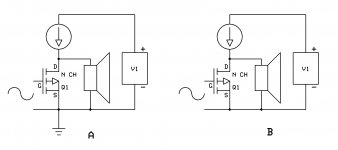
I'm sure we'd agree that A is a simplified diagram of a common source amplifier.
Despite the fact that B has no ground reference, we'd probably agree that the circuit will still work, that it will have current and voltage gain, and that it is still a common source amplifier even though we generally mean "grounded source" when we use the term. In this case, the signal and the source of the mosfet are attached to a common node.
Am I helping at all here? If not, just say so and I'll let the wizards take over.")
Here's the first.
I'm sure we'd agree that A is a simplified diagram of a common source amplifier.
Despite the fact that B has no ground reference, we'd probably agree that the circuit will still work, that it will have current and voltage gain, and that it is still a common source amplifier even though we generally mean "grounded source" when we use the term. In this case, the signal and the source of the mosfet are attached to a common node.
Am I helping at all here? If not, just say so and I'll let the wizards take over.
Attachments
And if we're still together after that have a look at C.
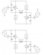
Can we agree to take two of those "floating" amps, eliminate the current sources by cross connecting the positive terminals of their batteries so that each becomes a current source for the other and attach the speaker between their drains?
Do we have any reason to believe that it won't still have current and voltage gain?
If you answered no, have we achieved liftoff?
Attachments
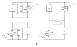
If a positive going AC signal is seen at input of left side, an amplified but inverted copy is seen on that same fets drain. This is what the load sees from the left side fet. That same amplified and inverted signal is also seen by the source of the of the right hand fet and is amplified once again, common gate style. So the load sees on its right side, a slightly larger copy of what is on its left side. Being push pull, only the difference is amplified. If any V gain is taking place, this is the only way i see it happening. I will say that all the above could be completely wrong and based on a bad premise.
In the first paragraph of your article subtitled " Input Stage", you say that left as is with just an input buffer as FE we would have an amp that works, but would have less than unity gain. has your understanding changed since the article?
I'm failing to communicate, so I'll save you some time and give you the short, effective, but incomplete answer: Yes. I believe there is more on that in the thread you got the Nelson Pass quote from.
Not at all. We're all learning.
I recall you wanted to pursue a scaled down version. Why not buy some cheap little FETs and see what happens?
The trouble with building and testing these things is that they require balanced or even floating balanced input signals and a scope or analyzer that can accept a truly balanced signal.
There's always the simulator.
I suggest trying some of these circuits with real (or virtual) electricity, observe what happens and then worry about why it happens.
Last edited:
- Status
- This old topic is closed. If you want to reopen this topic, contact a moderator using the "Report Post" button.
- Home
- Amplifiers
- Pass Labs
- BA-C