I did not make one, but I probably could.
What dimensions? Are you mounting outputs on the board?
What are the hole placements?

Hello Nelson,
I would want to mount the outputs on the board - well on the edge of the board I guess?
Mono boards and I was hoping to use the IRFP240's that I have assuming they can do the duty.
Dimensions are not critical would design the box around them...
I really dont know how you find the time to be so active in this forum and produce all the kit you do as well!
Much obliged.
WM
I would totally buy a PLH board.
Yes I am sure the list here will grow!
Nelson one other thing I have just thought of - I would want the version with paralleled output devices i.e Fig 11 in your writeup?
Thanks again.
WM
Here is the schematic. I have ordered the PCBs, and as soon I receive them, I can start mounting the components before initial testing.
I plan to use a 2x18 V 500VA transformer common for the two channels. I also have two quite large heatsinks (0.3 K/W) which I plan to use. This amplifier favours high quiescent current, so maybe I can set this as high as 1.8 A...
I plan to use a 2x18 V 500VA transformer common for the two channels. I also have two quite large heatsinks (0.3 K/W) which I plan to use. This amplifier favours high quiescent current, so maybe I can set this as high as 1.8 A...
Attachments
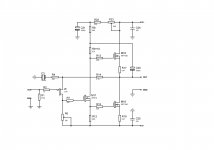
Yes I know what you mean. I have not quite decided yet if I am going to use a pot as done in the PLH amplifier. For the time being I have thought of using to resistors instead of the pot and then have the possibilty to change between push pull and something like halfway single ended.
Here is the schematic. I have ordered the PCBs, and as soon I receive them, I can start mounting the components before initial testing.
I plan to use a 2x18 V 500VA transformer common for the two channels. I also have two quite large heatsinks (0.3 K/W) which I plan to use. This amplifier favours high quiescent current, so maybe I can set this as high as 1.8 A...
This is certainly looking good to me! - Nelson can help crit the design I am not up to that - but I mean the concept and the components!
I have a pair of Conrad MF35-151.5 heatsinks rated at 0.21C/Watt and I have IRFP240s - so yes very happy with the direction this is going knutn!
Thanks
WM
Last edited:
Knut,
You can balance the drive on the output transistors by splitting the 0.47 ohm sense resistor into a centre tapped pair of 0.235 ohms, with the the feedback resistor R14, the bootstap capacitor C20 and the loudspeaker connected to the same point. I used this approach in the latest version of my interpretation of ZenV4 - similar topology to J Aleph.
See: http://www.diyaudio.com/forums/pass-labs/161716-aleph-current-source-mod.html
- Status
- This old topic is closed. If you want to reopen this topic, contact a moderator using the "Report Post" button.
- Home
- Amplifiers
- Pass Labs
- JLH/PLH PC Boards?