In my attempt to corner the market on used 5200's, I now have a newer updated GFA-5200 to play with (date sticker says 3-97). It has separate windings for the input stage, so input rails are +/-54V while output stage rails are ~42V. (Maybe it can swing the full output rails?) Then it also has separate PS (bridge rectifiers and caps) for each channel, so a useful advantage over the original.
It appears to have been assembled very quickly, and the input signal cable is actually RESTING on one of the rectifier bridges, so clearly cable routing is not one bit important to these hacks. Nor is capacitance: It has only 4 puny 6800uF caps, so it needs some help getting the PS ripple down from an unacceptable ~50mV.
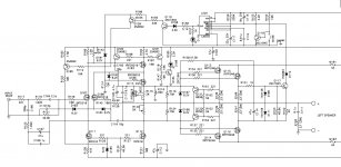
Now, "protection" is something they obsessed over: It has more transistors watching for faults (10) than for making sound (9). I will be referring to the schematic for the 5300 (attached) which is very close to the 5200.
It is my intention to replace the cover with a perforated aluminum cover which will be attached to the existing heatsink for maximum passive heat rejection without the use of a fan.
Stay tuned!
While not being anywhere near as facile with circuits (and this drawing does make it a little more confusing), any thoughts of trying to split C102 into a two-pole/TMC compensation to push more LF loop gain around the output transistors?
")
For years I sat on a borrowed oscope hoping to get around to the snubber cap and resistor, but could never bring myself to disconnect the amp from the system. I should find someone with a Quasimodo bellringer setup:
http://www.diyaudio.com/forums/powe...sformer-snubber-using-quasimodo-test-jig.html
http://www.diyaudio.com/forums/powe...sformer-snubber-using-quasimodo-test-jig.html
Exact opposite
I'm seeing minty beautiful board and transistors with nothing more than a light darkening in the areas of the resistors. Overall, nothing alarming at all.
Thanks.
Srinath.
Srinath, on yours the ps is common to both channels. One fuse is for the positive rail, and the other is the negative.
Are you saying yours has visibly blown output transistors on both L and R channels?
I'm seeing minty beautiful board and transistors with nothing more than a light darkening in the areas of the resistors. Overall, nothing alarming at all.
Thanks.
Srinath.
OK, I read it as if your transistors were cracked open...Awesome, I will get my transistor tester and get on it sometime after some of these already cracked open (snip)
sorry
No, I meant I will get to this amp after I get the "other already cracked open amps" worked on.
As in - I have a lot of projects in various states of progress toward repaired status.
Let me know what you think please. I suspect power supply side cos both fuses are blowing.
Thanks.
Srinath.
OK, I read it as if your transistors were cracked open...
No, I meant I will get to this amp after I get the "other already cracked open amps" worked on.
As in - I have a lot of projects in various states of progress toward repaired status.
Let me know what you think please. I suspect power supply side cos both fuses are blowing.
Thanks.
Srinath.
The fuses that blow inside of the amp are the rail fuses, they are after the main filtering caps and will not blow when one of the main filtering caps fails. The fuse on the rear panel will blow when a main filtering cap goes bad.
The fact that oversized 5A rail fuses were installed means that whatever was failing is almost certainly dead now. I would expect to have to replace the output mosfets in the affected channel.
Srinath, I agree with Chamberman.
(Although it's not necessary for the rear panel main fuse to blow with a bad PS cap; a bad cap will just make the ACV really high and the amp buzz in the output.)
You could satisfy yourself that the PS is fine by leaving out the rail fuses and measuring the PS DC voltage and AC voltage (ripple). If AC V is around 50mVAC or lower, then the PS is as designed. If the ripple is much higher then it will need new PS smoothing caps.
You could then load test the PS by loading it with a suitable power resistor, the value of which I will leave for you to calculate.
ps. It's likely somebody put in 5A rail fuses instead of the original 4A because that's all that Radio Shack had available, but that's a red herring.
That's what got me thinking that its power supply - its both channels, and at the same time.
I have a few that are blowing 1 channel. That I know is transistors in that channel.
I guess the answer is still to test them and replace as needed.
Thanks.
Srinath.
You're not talking about a lot of money, there's only a single IRF N and P output device in both channels, just replace them in both channels. The nice thing is that you do not have to worry about VGS matching. I'd also go ahead and install a new 9610 & 610 predrive mosfet while you've got it apart. Once again, not a lot of money to repair these Adcoms and you've got some good piece of mind once you're done, not to mention the channels will have matching parts from the same manufacturer in both channels.
You might also want to look at replacing the bias pots, the ones on the 5400 I tinkered with were extremely cheap. I replaced them with 10 turn cermets. If you do replace them, measure the resistance of the old ones once they are removed and try to set the new ones approximately back to where they were. This should get you close and only require a mild tweak to get the bias into spec.
I picked one of these up too
I saw a GFA-5200 and its matching preamp up for sale on Craigslist yesterday. Normally I would pass by a smaller amp like this but both units were pristine and the pair was $100. The preamp was listed as fully functional and the amp said "blowing fuses". This was right up my alley.
I have never been inside a piece of Adcom gear but I can distinctly remember lusting over a white GFA-555 sitting in the local audio boutique in the mid 80's. Since this is a Pass design I thought I would jump in. What do I have to lose?
One of the rail fuses was blown. I dont know how both fuses survived as the complimentary pair of output mosfets on one channel were baked short. There were also two small caps sizzling and bleeding onto the PCB. I replaced the caps and yanked the bad output transistors and found myself with an amp that powers up and plays, albeit only on one channel until I can order the replacement mosfets.
Now here is where I get a little frazzled. I am looking over the PCB and see what appears to be tons of re-work by Adcom. You know the type of re-work that says "Oops, engineering made a boo-boo; let's fire Teddy and lets fix it in post production!"
Is what I am seeing errors that have been corrected or is this someone else attempting aftermarket MOD's to improve the amp? I was a little disappointed to see that much appended electronics.

Thanks!
I saw a GFA-5200 and its matching preamp up for sale on Craigslist yesterday. Normally I would pass by a smaller amp like this but both units were pristine and the pair was $100. The preamp was listed as fully functional and the amp said "blowing fuses". This was right up my alley.
I have never been inside a piece of Adcom gear but I can distinctly remember lusting over a white GFA-555 sitting in the local audio boutique in the mid 80's. Since this is a Pass design I thought I would jump in. What do I have to lose?
One of the rail fuses was blown. I dont know how both fuses survived as the complimentary pair of output mosfets on one channel were baked short. There were also two small caps sizzling and bleeding onto the PCB. I replaced the caps and yanked the bad output transistors and found myself with an amp that powers up and plays, albeit only on one channel until I can order the replacement mosfets.
Now here is where I get a little frazzled. I am looking over the PCB and see what appears to be tons of re-work by Adcom. You know the type of re-work that says "Oops, engineering made a boo-boo; let's fire Teddy and lets fix it in post production!"
Is what I am seeing errors that have been corrected or is this someone else attempting aftermarket MOD's to improve the amp? I was a little disappointed to see that much appended electronics.
Thanks!
Attachments

Generatorlabs: Yours appears to be a very early 5200. Is there a date sticker on the rear? Country of origin?
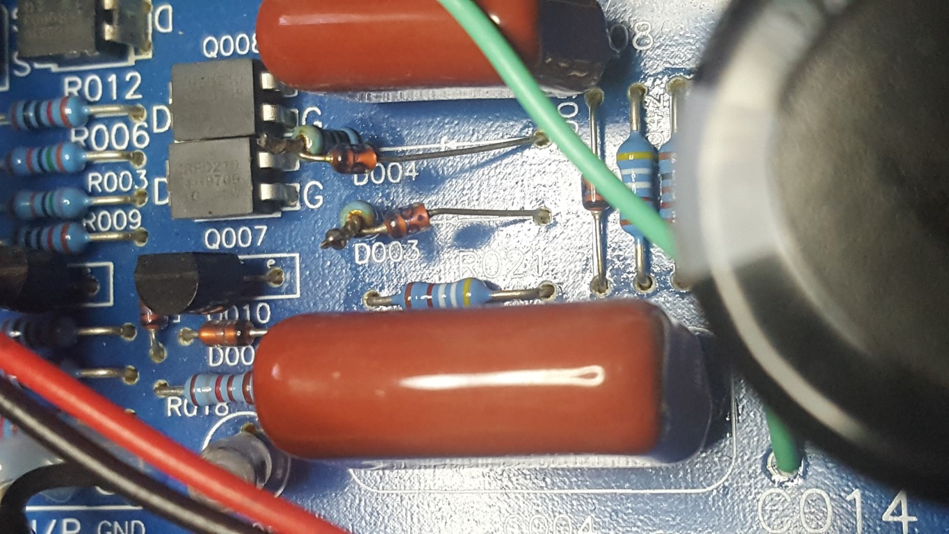
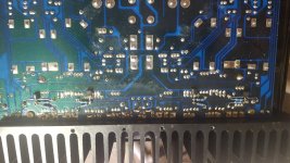
Until a 5200 schematic shows up, we can keep referring to the attached 5300. It appears the factory was adding Q121 and Q122 (for current limiting) to the underside of the pcb.
My earlier 5200 also has the diode and resistor tied together as shown in your photo, but has no rework or additions on the underside like yours.
I look forward to your updates! These GFA-5200's are diamonds in the rough...
Attachments
Generatorlabs: Yours appears to be a very early 5200. Is there a date sticker on the rear? Country of origin?
It says it is made in the Peoples Republic of China.
There is a small black sticker next to the serial number that has "2-97" on it.
I am guessing this is February of 97?
Right, I would also assume Feb 1997, so that's as if yours with the ton of rework has an earlier pcb than even my 1995 version (subject of this thread). Strange.
Here's my recollection/speculation: the earliest 5200 were made in Japan, then Taiwan, then later PR of China, and the latest ones were simply 'China.' F.ex my second 5200 has sticker '3-97' and PR of China, but it has dual mono PS as well as extra transformer windings for the input stage, so quite advanced. What's inside yours?
Here's my recollection/speculation: the earliest 5200 were made in Japan, then Taiwan, then later PR of China, and the latest ones were simply 'China.' F.ex my second 5200 has sticker '3-97' and PR of China, but it has dual mono PS as well as extra transformer windings for the input stage, so quite advanced. What's inside yours?
What's inside yours?
My unit looks exactly like the very first picture you put up in this thread.
This one:
Now that I really take a look at this I just realized this board does not have one relay on it. On the opposite side of the spectrum my Mark Levinson 332 must have at least 15 power and small signal relays that chatter up in sequence when powering it up! I still have no idea what most of the tiny signal relays actually do.
Hey guys cool you have this thread running. I am looking for a small not very hot amp for a friend of mine and Adcom came to my mind right away. Two questions:
1. Did Nelson really design that one as well (know about 5x5 line)?
2. How does it sound compare to 535 which would be my first candidate?
Thanks!
1. Did Nelson really design that one as well (know about 5x5 line)?
2. How does it sound compare to 535 which would be my first candidate?
Thanks!
That's a pic of my '95' and I'm pretty sure it doesn't have that stuff underneath (nor on-board), so it appears they added it on underneath to later versions (like yours). And then there is a jump to the '3-97' version which has everything on a larger pcb: dual mono PS, separate input stage windings, current limiting, plus the separate 12V supply.My unit looks exactly like the very first picture you put up in this thread.
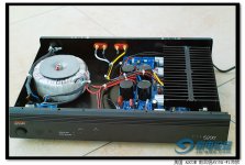
There's also the amp in attached pic that shows extra heatsinking, although I don't know if that came from the factory, or if someone modded it. It has a single PS, so is an earlier amp.
Attachments
Hey guys cool you have this thread running. I am looking for a small not very hot amp for a friend of mine and Adcom came to my mind right away. Two questions:
1. Did Nelson really design that one as well (know about 5x5 line)?
2. How does it sound compare to 535 which would be my first candidate?
Thanks!
In factory trim, I thought the 535 and the early 5200 sounded pretty dry, with the later 5200 a bit sharper but nothing noteworthy. More PS caps helped the 5200, but getting it to over 0.25A bias and under 10mV ripple 'fixed' it, and then more caps and more bias on top of that fixed it for good.
The 535 is a BJT amp, so it doesn't have the class A potential of the mosfet 5xxx series amps that Nelson also designed.
- Home
- Amplifiers
- Pass Labs
- Summer / Consolation Amplifier: 1995 Adcom GFA-5200