I forgot to post this:
When biased at 12mv I get 123 degrees F (50.5 degrees C)on the upper region of the heatsink.
I shot this measurement with an infra-red thermometer, immediately after sliding the top cover off. With the top cover off for 30 minutes the temp lowered to 113 degrees F (45 degrees C). Even with perforations in the top & bottom cover, cooling is reduced, to the order of 10 degrees F.
I believe this temp (50 C) was a target that Nelson mentioned earlier in this thread.
In my opinion, at this level, careful placement of the amp is crucial for proper convection. For me it means keeping no other component stacked on top. It is so typical to see the GFA pre-amp sitting on top of the amp in photos. I am keeping the amp on the top with an adequate gap on the bottom as well.
The sound of the amp is agreeable with me. I have pounded it pretty hard, with music and signal generator sweeps. I can easily get the yellow clipping LED's to dance but it is unrealistic to get much more out of an amp this size with the limited silicon muscles it has to push it along.
I like the way the heatsink is tied directly to the lower chassis with a number of screws however heat transfer into the floor pan is not optimal. I bet if I CNC'd a nice 10" x 10" piece of aluminum plate to form a new floor pan for the amp and tied the heat sink into that it could be more efficient. Or maybe I should just snap out of it, leave it stock and move on to more productive things")
Thanks for the weather report!
Certainly if one is going to play with the bias for a wider class A region, then one also needs to remember to leave some margin to get rid of the extra heat which comes from operating at the top of the class AB region, at its peak power (where the yellow lights flash).
It's a seductive little amp that will draw you in step by step. My purpose for getting one was to evaluate how good one transistor per rail could sound, so I could decide on how to build my own F5s (single or dual transistors; how quiet a PS? And what voltage rails?). I'm leaning toward dual, for long term reliability and drive-anything capability.
For the 5200 I've been mulling a simple replacement cover made from perforated 0.060inch thick aluminum sheet, connected to the HS with an aluminum block.
I don't think attaching a big piece of plate on the underside will improve the steady state dissipation so much while also making it take longer to reach steady state. But adding surface area to the top of the HS, like connecting the existing cover to the HS via a thick aluminum bar (the same way I connected the additional HS on mine), so you get conduction to the cover would be an easy add-on.
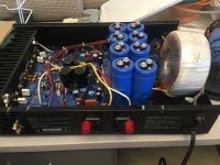
Ok so I got the amp. Later 5200 with separate psi for two channels. I am thinking now if I should just swap 4x6800uf caps for 4x22000uf, keep those on board bridges (I think the are 8A) and crank the bias up. Or... put new soft recover bridges from my FW amps off boards add 4 more caps off board to make CRC psu for each channel? Only concern is that it might be a bit too tight with that bigger board. BTW, do you actually need those 4A on the rails?
You're quick on the draw!
I don't think there exist larger caps than 15000uF in the size that will fit on the pcb (30mm Dia), so adding more caps off-board is your only option. But I haven't searched for a few years now, so we should have another look around.
I don't like the idea of rectifier bridges so close to the amp, so I placed mine off-board (see pic in post 11).
The 4A rail fuses are there to protect itself... Perhaps it would be nice with a bit of capacitance on the other side of the fuses, closer to the output transistors?
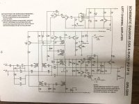
Adcom GFA 5200 Measurements
https://www.audiosciencereview.com/forum/index.php?threads/adcom-gfa-5200-measurements.36171/
Some graphs


https://www.audiosciencereview.com/forum/index.php?threads/adcom-gfa-5200-measurements.36171/
Some graphs