My F5 project is almost down to finishing, I used 2SK175/2SJ55, one set.
The first measurements are very seducing:
Bandwidth > 1.000 kHz at 5 V RMS. Go think that.
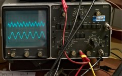
Square wave: both channels have just the slightest and well damped overshoot, loaded on 4 or 8 ohm . Example: Square wave, 100 kHz, 4 ohm NI load
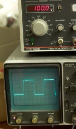
Square ware, unloaded
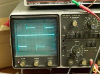
In this second picture you can see spurious overshoot that has some UHF components, maybe due to the long lead wires.
Photo 900 kHz on 4 ohm non-inductive load, at -3 dB
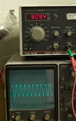
This is an incredible result, where 0 dB is 3,3 V RMS. And the board is underneath the chassis, the FETS are attached with 15 cm wires to the massive heat sinks on the side of the cabinet. Anyway, there is no sign of slew rate limiting, it is still a recognizable sine. But a square is not possible at that frequency.
Before connecting the output I measured the bandwidth of just the input: about 400 kHz at -3dB. [I test every component and half circuit as if it is an independent module].
The first measurements are very seducing:
Bandwidth > 1.000 kHz at 5 V RMS. Go think that.
Square wave: both channels have just the slightest and well damped overshoot, loaded on 4 or 8 ohm . Example: Square wave, 100 kHz, 4 ohm NI load

Square ware, unloaded

In this second picture you can see spurious overshoot that has some UHF components, maybe due to the long lead wires.
Photo 900 kHz on 4 ohm non-inductive load, at -3 dB

This is an incredible result, where 0 dB is 3,3 V RMS. And the board is underneath the chassis, the FETS are attached with 15 cm wires to the massive heat sinks on the side of the cabinet. Anyway, there is no sign of slew rate limiting, it is still a recognizable sine. But a square is not possible at that frequency.
Before connecting the output I measured the bandwidth of just the input: about 400 kHz at -3dB. [I test every component and half circuit as if it is an independent module].
Some measurements on this 1M-F5
Power output and distortion
DC current: 1,8 amp, power rails 20 V / 20 V.
Max power, set to when slight clipping sets in on scope.
2 ohms, 7 V RMS, 25 watt
4 ohms, 9 volt RMS 20 watt
8 ohms, 11 V, 15 watts
As you see, this does not qualify as a burning amp. But with 175 Watt idle from the mains, it does …
At 8 ohm, I get a damping factor of 20.
I found this formula: DF = V1 / (V2-V1)
V1 = output voltage of the amplifier with load resistor connected (8,71V)
V2 = output voltage of amplifier without a load (8,28 V).
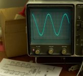
foto clipping
Nice behaved.
Channel balance: -0,040 db … unloaded, and loaded with 8 ohm: -0,063 db …
I obtained this result by careful selecting the feedback pairs.
Power output and distortion
DC current: 1,8 amp, power rails 20 V / 20 V.
Max power, set to when slight clipping sets in on scope.
2 ohms, 7 V RMS, 25 watt
4 ohms, 9 volt RMS 20 watt
8 ohms, 11 V, 15 watts
As you see, this does not qualify as a burning amp. But with 175 Watt idle from the mains, it does …
At 8 ohm, I get a damping factor of 20.
I found this formula: DF = V1 / (V2-V1)
V1 = output voltage of the amplifier with load resistor connected (8,71V)
V2 = output voltage of amplifier without a load (8,28 V).

foto clipping
Nice behaved.
Channel balance: -0,040 db … unloaded, and loaded with 8 ohm: -0,063 db …
I obtained this result by careful selecting the feedback pairs.
I seem to recall that a stock F5 does just about that with -3 dB at 1 MHz,
but I didn't record data that high, not seeing the point...

I hope to surprise you even more, later
Power supply
I made a full and complete star earth.
photo's of the starred earth
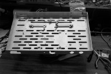
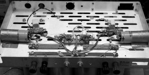
As diodes I used hefty diodes: 1N3891, fast recovery rectifier, 200 V, 12 A RMS continuous. They are mounted on a heat sink.
I have in first instance used a CLCRC power supply So the two rails have a different voltage (19,7 and 18,5 volt). The first cell has a 2.500 muF; then an inductor; the second cell 50.000 muF; with 0,22 ohm to the final cell 2*68.000 muF; with the scope I saw that the fluctuations from the power sector are very very low (a few mV only up and down). Nevertheless, bandwidth and power specs are even obtained with this lopsided power supply.
The inductors in the power supply are very effective. They are double-C. RMS hum reduces :
V-, raw 19,5Vdc; AC 1,9 volt in the first cell to 3,1 mV (-55 dB !!!!) in the second cell and 2 mV in the final cell ;
V+, raw 18,5 Vdc; AC 2,2 volt in the first cell to 6,6 mV in the second cell and 3 mV in the final cell.
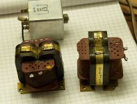
These DC differences had to be sorted out - are the two inductors different or are the two initial capacitors different? But I bought the inductors cheap in a dump shop, so if they differ, can't buy others anymore. If it is the capacitor, then I can swap the caps.
I tested the caps, these are 2.600 and 2.700 muF respectively. OK. It was the two inductors that do have different specs (though look the same): 0,56 ohm and 1,12 ohm.
I changed to normal resistors and changed the first cell of the power supply from CLC to CRC type. With a 0,47 ohm resistor I get:
both V+ and V-, raw 19,5Vdc; AC 1,1 volt in the first cell to 65 mV (-25 dB only) in the second cell and 3,9 mV in the final cell ; final cell has 19,70 dc volt both halves.
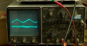
The line perturbation can now be seen on the scope on the power supply but not on the output; the power supply noise is cancelled (which was not the case with the mis-matched inductors).
If I want to go sophisticated, I can make a shunt in the second cell. In my Le Monstre (an 8W design by Hiraga, in broad lines comparable with the F5) I have implemented a shunt power supply. This is very effective for the background details.
I made a full and complete star earth.
photo's of the starred earth


As diodes I used hefty diodes: 1N3891, fast recovery rectifier, 200 V, 12 A RMS continuous. They are mounted on a heat sink.
I have in first instance used a CLCRC power supply So the two rails have a different voltage (19,7 and 18,5 volt). The first cell has a 2.500 muF; then an inductor; the second cell 50.000 muF; with 0,22 ohm to the final cell 2*68.000 muF; with the scope I saw that the fluctuations from the power sector are very very low (a few mV only up and down). Nevertheless, bandwidth and power specs are even obtained with this lopsided power supply.
The inductors in the power supply are very effective. They are double-C. RMS hum reduces :
V-, raw 19,5Vdc; AC 1,9 volt in the first cell to 3,1 mV (-55 dB !!!!) in the second cell and 2 mV in the final cell ;
V+, raw 18,5 Vdc; AC 2,2 volt in the first cell to 6,6 mV in the second cell and 3 mV in the final cell.

These DC differences had to be sorted out - are the two inductors different or are the two initial capacitors different? But I bought the inductors cheap in a dump shop, so if they differ, can't buy others anymore. If it is the capacitor, then I can swap the caps.
I tested the caps, these are 2.600 and 2.700 muF respectively. OK. It was the two inductors that do have different specs (though look the same): 0,56 ohm and 1,12 ohm.
I changed to normal resistors and changed the first cell of the power supply from CLC to CRC type. With a 0,47 ohm resistor I get:
both V+ and V-, raw 19,5Vdc; AC 1,1 volt in the first cell to 65 mV (-25 dB only) in the second cell and 3,9 mV in the final cell ; final cell has 19,70 dc volt both halves.

The line perturbation can now be seen on the scope on the power supply but not on the output; the power supply noise is cancelled (which was not the case with the mis-matched inductors).
If I want to go sophisticated, I can make a shunt in the second cell. In my Le Monstre (an 8W design by Hiraga, in broad lines comparable with the F5) I have implemented a shunt power supply. This is very effective for the background details.
Mechanical
A bit overdone, but I had these big heat sinks, and I planned to go this big capacitor route.
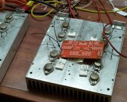
As you see, I have implemented an array of 4 pairs of FETS for each channel, I have the intent on paralleling.
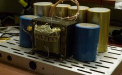
Front side
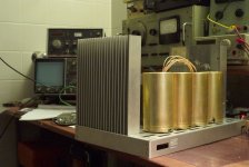
Maybe ugly in proportion, specifically if you note it just is a 20 Watt Monster.
With this array, I might go BA-2 and make a passive output stage, using the F5 board just as a BA-3 driver (with reduced current of course).
A bit overdone, but I had these big heat sinks, and I planned to go this big capacitor route.

As you see, I have implemented an array of 4 pairs of FETS for each channel, I have the intent on paralleling.

Front side

Maybe ugly in proportion, specifically if you note it just is a 20 Watt Monster.
With this array, I might go BA-2 and make a passive output stage, using the F5 board just as a BA-3 driver (with reduced current of course).
Parts and components (1)
I used the F5 boards from Jims audio store. Very well made, truly military grade. I like it that they are a bit bigger so leaves room for parts. Though some want to create a smaller board (Peter) with the shortest signal path, this board allowed me this bandwidth of 1+ MHz.
I have thought about the cascode (CViller in DIYshop) because the thermal load on the input will be constant (if you implement the cascade correctly), it will give slightly more 2nd harmonic, and some say the sound is more dynamic. By hey, look at a bandwidth of over 1 MHz - do I need more dynamics???
The 2SK170/2SJ74 input pairs. I bought matched input sets from AudioFet (Alweit) on ebay. These are marvelously paired. I tested them beforehand on both Idss @ 10 V and next on 20 V with source resistors of 0, 5, 10, 15, 20, 25 ohms.
I also tested the sets when I still had no output attached: equal across the both channels within 0,5 dB. I must say, Aleit did a very good job . It is not necessary at all to use different source resistors as EUVL suggested with these pairs.
How he packs them is shows his care.
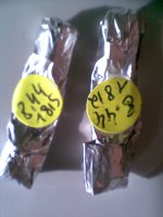
View attachment 2SK170, 2SJ74 pairs.pdf
specs of the inputs: impressive
Note that due to thermal drift, I cannot show best matching measurements, I doo it statically (not with pulse like a professional tester will do)
(Note: Previously I had bought unmatched jFETS elsewhere, but these measured all over the place while the 2SJ74's were fakes. So really go for a dependable source with matched pairs like AudioFet.)
As drain load for the input I choose 680 ohm carbon film (has low inductance) // 5 k 25 turns pot. For these transistors 560 ohms works OK too (for other FETS this resistor will be higher).
I used the F5 boards from Jims audio store. Very well made, truly military grade. I like it that they are a bit bigger so leaves room for parts. Though some want to create a smaller board (Peter) with the shortest signal path, this board allowed me this bandwidth of 1+ MHz.
I have thought about the cascode (CViller in DIYshop) because the thermal load on the input will be constant (if you implement the cascade correctly), it will give slightly more 2nd harmonic, and some say the sound is more dynamic. By hey, look at a bandwidth of over 1 MHz - do I need more dynamics???
The 2SK170/2SJ74 input pairs. I bought matched input sets from AudioFet (Alweit) on ebay. These are marvelously paired. I tested them beforehand on both Idss @ 10 V and next on 20 V with source resistors of 0, 5, 10, 15, 20, 25 ohms.
I also tested the sets when I still had no output attached: equal across the both channels within 0,5 dB. I must say, Aleit did a very good job . It is not necessary at all to use different source resistors as EUVL suggested with these pairs.
How he packs them is shows his care.

View attachment 2SK170, 2SJ74 pairs.pdf
specs of the inputs: impressive
Note that due to thermal drift, I cannot show best matching measurements, I doo it statically (not with pulse like a professional tester will do)
(Note: Previously I had bought unmatched jFETS elsewhere, but these measured all over the place while the 2SJ74's were fakes. So really go for a dependable source with matched pairs like AudioFet.)
As drain load for the input I choose 680 ohm carbon film (has low inductance) // 5 k 25 turns pot. For these transistors 560 ohms works OK too (for other FETS this resistor will be higher).
Last edited:
Parts and components (2)
Output with 2SK175 / 2SJ55, in a big TO-3 housing.
My output FETS were bought on the local market in Guangzhou from a surplus refurbishing shop ( I bought 22 pairs, costed a 'small fortune'); they measure exceptionally well. The 2SK175 / 2SJ55 has slightly higher specs than the more commonly known 2SK135/2SJ50: a higher current, voltage and a higher power - 125 watt against 100 watt). They have been used in very high end audio amplifiers. The Ciss is 2SK175 = 700 pF, 2SJ55 = 1.000 pF, about half of the stock F5 outputs.
I have implemented four pairs per channel, but first only connected one pair.
2SJ55
# @100 mA @600mA delta, + 0,5A=
1 0,647 1,520 0,87
2 0,664 1,616 0,95
3 0,671 1,603 0,93
4 0,705 1,573 0,87
5 0,714 1,656 0,94
6 0,716 1,647 0,93
7 0,718 1,638 0,92(Tested with a current source LM323 and a 50ohm/10 ohm resistor, fet in air, so does not consist of a good test, but adequate for matching; all readings after 5 seconds)
I flesh mounted them on the heatsinks, took me quite a time [days] with the precision drilling, cutting the screw mount, and ensuring there is no short-circuit between source and heatsink. You cannot drill this precision by hand.
Gate resistors: I soldered 100 ohms allan bradley pressed carbon resistors (these are non-inductive) on the gates; and inserted similar resistors in the boards, so both ends of the gate connecting wires have a resistance. I ensured the drain wire is physically routed separate from the gate wire.
Source resistors: I used 0,47 ohm Fukushima Futuba drains resistors (non-inductive, cemented, 6 W), selected, with the highest value for the 2SK175 and the lowest for the 2SJ55 (because the knee is slightly different, about 200 mV between the units). That will give a near equal driving voltage in the input.
They do get very hot to the touch at 1,5 - 1,8 amps dc, so bolting them to the chassis with a washer or giving them a heat sink is really mandatory for the amplifier to remain stable over the years. These resistors have pins that get loose very quick, be cautious when bending!
These non-inductive resistors are a key to the bandwidth.
Current limit: I did implement the current limiter, at approx. 6 amps (safe, very safe margin for this MOSFET that can handle 9 amp pulsed at 10 volt ds), by using 820 ohms/200 ohms divider network instead of 1k/150.
I have not used the thermistor - the 2SK175 / 2SJ55 have a very nice negative temperature compensation behavior. That is why I changed the drain resistors for the input pairs.
Output with 2SK175 / 2SJ55, in a big TO-3 housing.
My output FETS were bought on the local market in Guangzhou from a surplus refurbishing shop ( I bought 22 pairs, costed a 'small fortune'); they measure exceptionally well. The 2SK175 / 2SJ55 has slightly higher specs than the more commonly known 2SK135/2SJ50: a higher current, voltage and a higher power - 125 watt against 100 watt). They have been used in very high end audio amplifiers. The Ciss is 2SK175 = 700 pF, 2SJ55 = 1.000 pF, about half of the stock F5 outputs.
I have implemented four pairs per channel, but first only connected one pair.
2SJ55
# @100 mA @600mA delta, + 0,5A=
1 0,647 1,520 0,87
2 0,664 1,616 0,95
3 0,671 1,603 0,93
4 0,705 1,573 0,87
5 0,714 1,656 0,94
6 0,716 1,647 0,93
7 0,718 1,638 0,92
I flesh mounted them on the heatsinks, took me quite a time [days] with the precision drilling, cutting the screw mount, and ensuring there is no short-circuit between source and heatsink. You cannot drill this precision by hand.
Gate resistors: I soldered 100 ohms allan bradley pressed carbon resistors (these are non-inductive) on the gates; and inserted similar resistors in the boards, so both ends of the gate connecting wires have a resistance. I ensured the drain wire is physically routed separate from the gate wire.
Source resistors: I used 0,47 ohm Fukushima Futuba drains resistors (non-inductive, cemented, 6 W), selected, with the highest value for the 2SK175 and the lowest for the 2SJ55 (because the knee is slightly different, about 200 mV between the units). That will give a near equal driving voltage in the input.
They do get very hot to the touch at 1,5 - 1,8 amps dc, so bolting them to the chassis with a washer or giving them a heat sink is really mandatory for the amplifier to remain stable over the years. These resistors have pins that get loose very quick, be cautious when bending!
These non-inductive resistors are a key to the bandwidth.
Current limit: I did implement the current limiter, at approx. 6 amps (safe, very safe margin for this MOSFET that can handle 9 amp pulsed at 10 volt ds), by using 820 ohms/200 ohms divider network instead of 1k/150.
I have not used the thermistor - the 2SK175 / 2SJ55 have a very nice negative temperature compensation behavior. That is why I changed the drain resistors for the input pairs.
Last edited:
Parts and components (3)
Current limit: I did implement the current limiter, at approx. 6 amps (safe, very safe margin for this MOSFET that can handle 9 amp pulsed at 10 volt ds), by using 820 ohms/200 ohms divider network instead of 1k/150.
I have not used the thermistor - the 2SK175 / 2SJ55 have a very nice negative temperature compensation behavior. That is also why I changed the drain resistors from 2.2 k to 680 ohm for the input drains.
I took very much care to select the feedback pairs, as I believe that a mismatched top/bottom half of the amplifier (they are both in parallel) will otherwise compete with each other, leading to oscillations. The top and bottom effectively are independent amplifiers, specifically so with the separate feedback loops of the F5.
View attachment selectie feedback pairs.pdf
See that it works out
First I bought 100 ohm 3W metal foil resistors (good within 0,1%, Sunpec) but later settled for 50 ohm carbon film because these allowed even tighter matching with the 10 ohm resistors that differed a bit more.
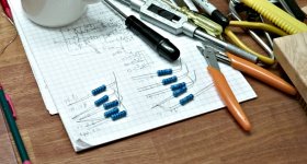

Set up procedure
Before starting, I had tested what bias is needed on the outputs (about 1,6 V for 0,5 amp); from that I had selected an inpout drain resistance that gives a good amount of adjustment (680 ohm//5k trim pot).
Set all pots to 0 ohms. I used a 0,5 amp current source (LM323 with 10 ohms load) to initiate the current on the plus side (2SK170/2SJ55), then I inserted a 4 ohm resistor, and balanced the bottom side (2SJ74/2SK175), this final balancing needs quite some iterations, I initially choose 0,8 volt over the 0,47 ohm (1,8 amp). [Some might think this is too complicated]
Instead of a 0,5 amp current source it is just as easy to connect a four ohm resistor and set the top to 0,5 amp (2 volts). This is what I did in the second channel. And then start to increase current on the other side. The whole current then balances to about 1,5 amp. The process works oh so sweet.
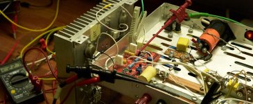
A very nice and quick procedure; compare that with the following: I once spent a day swapping fixed resistors on the Le Monstre that shares the basic topology with the F5 but uses fixed resistors . . .
The DC balance is very good, it stays within mV of zero, except on heavy load, then it will change a some 20-30 mV.
When I will parallel the outputs (later, in due time) then I will first set the current to about 0,5 amps (120 mV), altogether then I will watch the total current.
Before starting, I had tested what bias is needed on the outputs (about 1,6 V for 0,5 amp); from that I had selected an inpout drain resistance that gives a good amount of adjustment (680 ohm//5k trim pot).
Set all pots to 0 ohms. I used a 0,5 amp current source (LM323 with 10 ohms load) to initiate the current on the plus side (2SK170/2SJ55), then I inserted a 4 ohm resistor, and balanced the bottom side (2SJ74/2SK175), this final balancing needs quite some iterations, I initially choose 0,8 volt over the 0,47 ohm (1,8 amp). [Some might think this is too complicated]
Instead of a 0,5 amp current source it is just as easy to connect a four ohm resistor and set the top to 0,5 amp (2 volts). This is what I did in the second channel. And then start to increase current on the other side. The whole current then balances to about 1,5 amp. The process works oh so sweet.

A very nice and quick procedure; compare that with the following: I once spent a day swapping fixed resistors on the Le Monstre that shares the basic topology with the F5 but uses fixed resistors . . .
The DC balance is very good, it stays within mV of zero, except on heavy load, then it will change a some 20-30 mV.
When I will parallel the outputs (later, in due time) then I will first set the current to about 0,5 amps (120 mV), altogether then I will watch the total current.
Bandwidth is everything, next to phase
And that > 1 MHz claim . . . (yes, an F5 with o n e thousand kHz) bandwidth?
Easy at 8 ohm; with 4 ohm it drops to 910 kHz. And DC is also possible. My generator goes to 0,5 Hz - this is still not -3 dB.
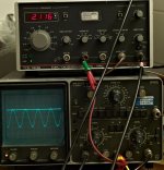
Surprise: A channel unloaded has a bandwidth of . . . an astonishing 2,1 MHz.
With 8 ohm it is 1,2 MHz, and with 4 ohm it is 910 kHz.
I'll gladly go for a lower bandwidth. This high bandwidth is a bit scary.
I do not have high frequency probes; I load the output with a 1,5 meter RG59 cable (300 pF) which might influence the result I see. The stray capacitance can be the reason the the peak on the screen; when going through the frequencies one does not see a high Q (maybe above 6 MHz?).
At these frequencies you will see slew rate limiting. And indeed if I run a square wave through, I will see limiting starting on the rising flank of the wave above 6/700 kHz, and soon it is a triangle.
I see a very small oscillation at 2,6 Mhz and a bigger one above 5,6 MHz (the highest my signal generator can go). This surely is due to capacitative coupling for instance of the lead wires and power supply interaction.
I connected a 2,7 nF silver mica across the 50 ohms feedback resistors: the bandwidth dropped to 650 kHz. Aklso, the unloaded square is now tightly controlled.
There is slightest ringing on the flanks (e.g. 300 kHz) more in one channel than in the other, probably dissymmetry in high frequencies.
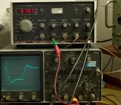
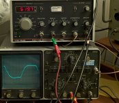
What I did was load a 470 capacitor across the output in (2). It shows the little series of straight lines, like a little slew rate (but it can't be slew rate as I see it).
Cures:
- I added a selected pair of 2,7 nF capacitors across the 50 ohm feedback resistors, selected pairs, tight matching is needed. Doesn't solve it.
- Maybe better : use input filter, 1k2 input loaded by 400 pF (low pass about 350 kHz). But this does not solve that smallest amount of ringing.
But neither helped.
- It could be balanced by adding a separate 300 pF gate/source capacitor on the 2SJ55 (because of its lower Ciss. Would this help?
- Or by adding slight different feedback caps.
Or implementing the trick in the version 2 F5 with a feedback fine-tuning pot.
Has anybody else bothered about this?
I decided to neglect this whole issue for the moment and . . listen.
And that > 1 MHz claim . . . (yes, an F5 with o n e thousand kHz) bandwidth?
Easy at 8 ohm; with 4 ohm it drops to 910 kHz. And DC is also possible. My generator goes to 0,5 Hz - this is still not -3 dB.

Surprise: A channel unloaded has a bandwidth of . . . an astonishing 2,1 MHz.
With 8 ohm it is 1,2 MHz, and with 4 ohm it is 910 kHz.
I'll gladly go for a lower bandwidth. This high bandwidth is a bit scary.
I do not have high frequency probes; I load the output with a 1,5 meter RG59 cable (300 pF) which might influence the result I see. The stray capacitance can be the reason the the peak on the screen; when going through the frequencies one does not see a high Q (maybe above 6 MHz?).
At these frequencies you will see slew rate limiting. And indeed if I run a square wave through, I will see limiting starting on the rising flank of the wave above 6/700 kHz, and soon it is a triangle.
I see a very small oscillation at 2,6 Mhz and a bigger one above 5,6 MHz (the highest my signal generator can go). This surely is due to capacitative coupling for instance of the lead wires and power supply interaction.
I connected a 2,7 nF silver mica across the 50 ohms feedback resistors: the bandwidth dropped to 650 kHz. Aklso, the unloaded square is now tightly controlled.
There is slightest ringing on the flanks (e.g. 300 kHz) more in one channel than in the other, probably dissymmetry in high frequencies.


What I did was load a 470 capacitor across the output in (2). It shows the little series of straight lines, like a little slew rate (but it can't be slew rate as I see it).
Cures:
- I added a selected pair of 2,7 nF capacitors across the 50 ohm feedback resistors, selected pairs, tight matching is needed. Doesn't solve it.
- Maybe better : use input filter, 1k2 input loaded by 400 pF (low pass about 350 kHz). But this does not solve that smallest amount of ringing.
But neither helped.
- It could be balanced by adding a separate 300 pF gate/source capacitor on the 2SJ55 (because of its lower Ciss. Would this help?
- Or by adding slight different feedback caps.
Or implementing the trick in the version 2 F5 with a feedback fine-tuning pot.
Has anybody else bothered about this?
I decided to neglect this whole issue for the moment and . . listen.
Distortion measurement
Because I have a electrostatic LS with a complex load the next test is very important: will the amplifier oscillate with a capacitative load? So I connected a capacitor across the output, and later used it with a damping resistor
Just a resistor (2n7 feedback cap):
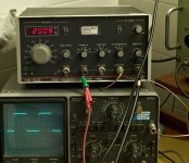
Overshoot with capacitative load, 8 ohms with 0,47 muF
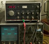
This is the ringing we saw earlier too.
foto overshoot 4 ohm parallel with cap 470 nF with a series 1 ohm resistor
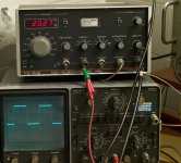
This is well damped.
This load can be made more complex with an inductor (i would have to look for the equivalent circuit of the Quad ESL57)
The little feedback capacitor of 2,7 nF stops the overshoot unloaded and reduces the ringing only a little bit. I would need 15 nF to really stop the ringing (I tried 21 nF but this was just a bit too much damping).
Distortion picture at 2,47 kHz
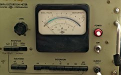
Predominant second harmonic and down near the noise floor.
Compare with Le Monstre distortion
The similar topology of Le Monstre with a cascode gave me 0,6% second harmonics. See my avatar.
Because I have a electrostatic LS with a complex load the next test is very important: will the amplifier oscillate with a capacitative load? So I connected a capacitor across the output, and later used it with a damping resistor
Just a resistor (2n7 feedback cap):

Overshoot with capacitative load, 8 ohms with 0,47 muF

This is the ringing we saw earlier too.
foto overshoot 4 ohm parallel with cap 470 nF with a series 1 ohm resistor

This is well damped.
This load can be made more complex with an inductor (i would have to look for the equivalent circuit of the Quad ESL57)
The little feedback capacitor of 2,7 nF stops the overshoot unloaded and reduces the ringing only a little bit. I would need 15 nF to really stop the ringing (I tried 21 nF but this was just a bit too much damping).
Distortion picture at 2,47 kHz

Predominant second harmonic and down near the noise floor.

Compare with Le Monstre distortion
The similar topology of Le Monstre with a cascode gave me 0,6% second harmonics. See my avatar.
Last edited:
Distortion measurement
Because I have a electrostatic LS with a complex load the next test is very important: will the amplifier oscillate with a capacitative load? So I connected a capacitor across the output, and later used it with a damping resistor
Just a resistor (2n7 feedback cap):
View attachment 242038
Overshoot with capacitative load, 8 ohms with 0,47 muF
View attachment 242039
This is the ringing we saw earlier too.
foto overshoot 4 ohm parallel with cap 470 nF with a series 1 ohm resistor
View attachment 242040
This is well damped.
This load can be made more complex with an inductor (i would have to look for the equivalent circuit of the Quad ESL56)
The little feedback capacitor of 2,7 nF stops the overshoot unloaded and reduces the ringing only a little bit. I would need 15 nF to really stop the ringing (I tried 21 nF but this was just a bit too much damping).
Distortion picture at 2,47 kHz
View attachment 242041
Predominant second harmonic and down near the noise floor.
View attachment 242042
Compare with Le Monstre distortion
The similar topology of Le Monstre with a cascode gave me 0,6% second harmonics. See my avatar.
I decided to neglect this whole issue for the moment and . . listen.
And...? How does it sound.
yesterday I moved it to the living room.
First impressions:
Pleasing.
Excellent. Much detail is transmitted, in depth.
Syllables and voices are having their own character, two singers in guet are clearly distinguished. No specific sound is projected (syllables).
What also surprises me is that the character remains stable when changing volume. [I first heard that on Hypex modules].
Low register is clear, the electrostats have the tendency to sound nasal; this is not [yet] heard either.
I cannot call the sound 'laid-back'.
Sound impressions
Second impression:
I was listening to Alfred Deller, accompanied by a pianoforte.
The details of a highly oversampling are now transmitted. Previously, the highs (in classical music) had the tendency to have a similar sound, now I can distinguish many high instruments and the complex notes of the instrument, also behind the players.
Differences between tracks are heard.
(Carla Bruni - on m'a dit) Small artifacts that the producer mixes in are heard, sound such as from the throat (coarse) can be heard.
Very very detailed, all due to the capacity to really dump a lot of current very fast in the electrostats.
My Meridian comes to life again!!!
The amp does sound as if it is very powerful.
The analogy in impression with the 8W Le Monstre is clear now for me. It is a Monster too: 15 W.
I can calculate the peak current (the formula is Vrms/0,7=Vp); what I did do is check what the voltage was (via scope, DC input) and that gave me around 15 V on 20 V power lines when clipping starts in, if i remember correctly, with 8 ohm. I did't check the others, but surely they are high too,
2 ohms, 7 V RMS, 25 watt (10Vp=5A peak)
4 ohms, 9 volt RMS 20 watt (13Vp, 3,2 Apeak)
- I could do is take out the current limiter 'output' and connect that to a LED via a 2-3 K resistor: if it blinks I hit my max. Great test for a lab setting.
I'll make square waves from low frequencies too but I'm afraid this will have to wait three weeks (travel ..)
albert
- Status
- This old topic is closed. If you want to reopen this topic, contact a moderator using the "Report Post" button.
- Home
- Amplifiers
- Pass Labs
- 1M-F5 - A 1 MHz F5 project
