It is a voltage clip.
The circuit has a gain of 6. So output is at 13.8V with 16V rails.
As expected not enough headroom left for the MOSFETs.
Since you are using 2 output pairs, you can increase rail voltage and reduce bias current per FET while keeping dissipation per FET below 32W.
I would try 20V 1.6A per FET as a start.
Patrick
Thanks Patrick
I thought about that but I use 22V Rails and 1.3A per FET.
Can you explain how you get the 6dB gain? With 6dB I get 4.4V out with 2.2V in. Wasn't it 15dB?
Last edited:
This is how I built one:
http://www.diyaudio.com/forums/pass...world-class-cascoded-balanced-xf5-budget.html
I used 1K and 100K as NP did in the original and have no problems.
Thanks for the help but this was solved a few posts before. 1k and 33.2k
Gain of 6, not 6dB (gain of 2).
The closed loop gain of a feedback amp is given by (Rfeedback + Rshunt) / Rfeedback.
In this case, Rfeedback = 50R, Rshunt = 10R.
So gain = (50+10)/10 = 6.
Patrick
I've got this wrong. Thank you for clearification.
Any idea why I get this clipping? With +/- 22V Rail I should be safe.
Your output voltage should not come closer than say 4V to the rail voltage if you want to avoid clipping.
The MOSFETs do not have sufficient Vds to operate properly.
Patrick
I understand that, but I'm missing a few Volts
Output with 2,3V in and gain of 6 (15,5dB) is 13,8V. With 22V Volt rail....
My PS is ultra stable. 800VA Transformer 2x18V, CLC with 2x99.000 uF, 2x 2,2mH/0,12Ohm.
You need to show an output waveform for the clipping for us to understand your problem.
Patrick
OK, I'll make several pics.
Measurements and Waveform 1kHz 8Ohm
Amp info:
Vrail +/- 21.8V
Ibias 0.6V across 0.47 Ohm 1.3A 2 parallel output Fets Total Bias 2.6A
I out of PS measured 5.4A
NOT X-ed yet.
1. 8 Ohm 2.5Vin 0.5%THD right before clipping
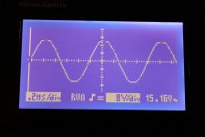
2. 8 Ohm 2.6Vin 1.5%THD start of clipping
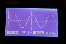
3. 8 Ohm 2.8Vin 4.5%THD clipping
Amp info:
Vrail +/- 21.8V
Ibias 0.6V across 0.47 Ohm 1.3A 2 parallel output Fets Total Bias 2.6A
I out of PS measured 5.4A
NOT X-ed yet.
1. 8 Ohm 2.5Vin 0.5%THD right before clipping
2. 8 Ohm 2.6Vin 1.5%THD start of clipping
3. 8 Ohm 2.8Vin 4.5%THD clipping
Attachments
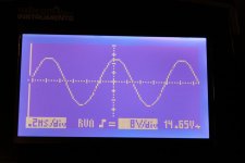
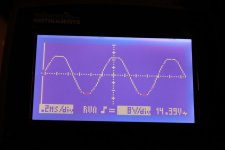
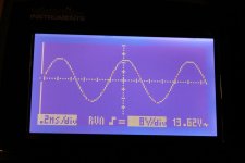
It looks like the voltage displayed on your "oscilloscope" is Vrms.
The peak to peak amplitude is approximately 5 divisions x 8V = +/-20V approximately.
Assuming that is the case, then the input voltages you quoted are also Vrms.
2.8Vrms = +/- 3.96V Vin
3.96V x gain of 6 = 23.8V Vout > Vrails.
This should explain the voltage clipping which is clearly visible.
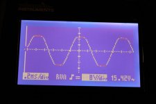
Reducing Vin to 2.1Vrms should give you, IMHO, the correct max. output according to your chosen rail voltages.
Patrick
.
The peak to peak amplitude is approximately 5 divisions x 8V = +/-20V approximately.
Assuming that is the case, then the input voltages you quoted are also Vrms.
2.8Vrms = +/- 3.96V Vin
3.96V x gain of 6 = 23.8V Vout > Vrails.
This should explain the voltage clipping which is clearly visible.
Reducing Vin to 2.1Vrms should give you, IMHO, the correct max. output according to your chosen rail voltages.
Patrick
.
Last edited:
It looks like the voltage displayed on your "oscilloscope" is Vrms.
The peak to peak amplitude is approximately 5 divisions x 8V = +/-20V approximately.
Assuming that is the case, then the input voltages you quoted are also Vrms.
You are absolutely right!
My HP Audio Analyzer was also set to RMS reading.
Thank you!
Amp Data and Changes made to schematic.
Design
Amp Boards X-ed as described at the beginning of this thread
Post #1
Amp Data
- Transformer 800VA, 2x18V per mono block
- PS CLC 2x 33.000uF 33.000uF 2.2mH/0.12Ohm 33.000uF; total 198.000uF per mono block
- Vrail +/- 21.8V
- Ibias 1.3A per output FET (gives 0.29V across R11/12), 2 output pairs! X-ed 4 output pairs
- output FETs IRFP240/IRFP9240
- input Fets 2SJ74BL/2SK170BL
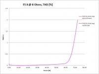
- app. 70W into 8 Ohms, voltage clipping
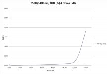
- app. 130W into 4 Ohms, voltage clipping
- app. 175W into 2 Ohms, voltage clipping
- app. 200W into 1 Ohms, current clipping
Changes made to schematic
R10 = 33,2k
R21/22 = 22k
R17/R18 = 702
R117/R118 open
R11/R12/R111/R112 = 0.22
That’s it.
Design
Amp Boards X-ed as described at the beginning of this thread
Post #1
Amp Data
- Transformer 800VA, 2x18V per mono block
- PS CLC 2x 33.000uF 33.000uF 2.2mH/0.12Ohm 33.000uF; total 198.000uF per mono block
- Vrail +/- 21.8V
- Ibias 1.3A per output FET (gives 0.29V across R11/12), 2 output pairs! X-ed 4 output pairs
- output FETs IRFP240/IRFP9240
- input Fets 2SJ74BL/2SK170BL
- app. 70W into 8 Ohms, voltage clipping
- app. 130W into 4 Ohms, voltage clipping
- app. 175W into 2 Ohms, voltage clipping
- app. 200W into 1 Ohms, current clipping
Changes made to schematic
R10 = 33,2k
R21/22 = 22k
R17/R18 = 702
R117/R118 open
R11/R12/R111/R112 = 0.22
That’s it.
Last edited:
Design
Amp Boards X-ed as described at the beginning of this thread
Post #1
Amp Data
- Transformer 800VA, 2x18V per mono block
- PS CLC 2x 33.000uF 33.000uF 2.2mH/0.12Ohm 33.000uF; total 198.000uF per mono block
- Vrail +/- 21.8V
- Ibias 1.3A per output FET (gives 0.29V across R11/12), 2 output pairs! X-ed 4 output pairs
- output FETs IRFP240/IRFP9240
- input Fets 2SJ74BL/2SK170BL
- app. 70W into 8 Ohms, voltage clipping
- app. 130W into 4 Ohms, voltage clipping
- app. 175W into 2 Ohms, voltage clipping
- app. 200W into 1 Ohms, current clipping
Changes made to schematic
R10 = 33,2k
R21/22 = 22k
R17/R18 = 702
R117/R118 open
R11/R12/R111/R112 = 0.22
That’s it.
I salute you!
I was told a Balanced F5 with the IRFP outputs would not work by some very visible people on this forum. I'm glad you proved it could be done!

Could you perhaps show a THD plot below 0.05%?
Yes, together with pics but I'm out a few days
Perhaps of more interest a FFT plot of the relative distribution of K2, K3, K4, ...
Firstly of each single ended output to Gnd, then in differential mode.
Patrick
My Audio Anlayzer is not equipped for this.
Expert Advice...
I can still use other output devices when I don't like the sound. But I like it
")
- Status
- This old topic is closed. If you want to reopen this topic, contact a moderator using the "Report Post" button.
- Home
- Amplifiers
- Pass Labs
- F5X from diyAudio Boards P-F5c-2V20e