Hi all, recently I had this problem: One IRFP240 of left channel aleph2 got blown, source resistor got burnt to bits. It was the mosfet on the amplifier bank (V- side), not the current source. After replacing the mosfet, everything returned to normal but not for long....
Using an AC clamp meter, I turned on the amp while monitoring the current draw. Normal operation is about 1A@230v. After about an hour, using an IR thermometer, the heatsink reads ~50 degC, while each mosfet is about ~60degC.
During listening, the meter suddenly registers 5A@230v, while music is replaced by a loud humming sound (Can't be DC if there's sound right? Not sure if it's mains 50hz also.). At this point, I turn off the amp immediately. After that, I can turn on the amp again, and everything returns to normal. But then it happens again, randomly.
This only happens in one channel, the current draw as stated is 1A@230v. The other channel is ok, operating at 0.8A@230v, it also runs about 2degC cooler than the other channel.
Help guys! How can I make the amp more stable?
Attachments
Maybe the problem is layout dependent . Especially if you made very distant tracks on the PCB , or P2P wiring , capacitance in the feedback resistor region / or lag compensation capacitor / or current source capacitor is not adequate in value .
Concerning the lag capacitor , sometimes you need one sometimes not . Use oscillo to confirm .
The problem could also be a ground / earth loop problem , this can go to oscilation problems with amps .
Try change some small capacitors values , and monitoring the amp with an oscilloscope ( you have some friends can let you one) to see if your squarewaves are free from oscilations .
With some Aleph 2 mono blocs I had ground loop problems . You know what ? using both amps together I got some smoke on one inductor of the PSU ...
Try to verify no ground loops . Isolate all grounds from chassis . Connect earth directly to chassis , and use a thermistor or a 4R7 / 5 W to join PSU ground to earth on each mono bloc . Then , Use a 3 R/ 5W resistor to link PSu ground to circuit ground . on each mono bloc .
Regards
Anael
nar,
I used all standard values of the aleph2 schematic. By the lag capacitor, do u mean increasing the 10pf (C8)? I could probably borrow a scope to try it out, but I may have some problems generating the square waves....
Speaking of ground lines, I did measure a 0.3amp AC from earth to PSU ground on the faulty amp, but 0.1amp on the ok amp (both during normal operation). Don't know why this current exists, but it does.
My earth line is connected directly to the chassis, then to the PSU caps thru a 25R thermistor. Circuit ground is currently tied to PSU ground. If I use a 3R resistor from PSU to circuit ground, do I tie the speaker -ve terminal to circuit ground or PSU ground?
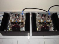
Really puzzles me, both monoblocs were built as identical as possible, as you can see even the wiring lengths & routing flows the same way. But only 1 channel has this problem. Maybe I really have the same problem of ground loops as you, how do I tell?
I used all standard values of the aleph2 schematic. By the lag capacitor, do u mean increasing the 10pf (C8)? I could probably borrow a scope to try it out, but I may have some problems generating the square waves....
Speaking of ground lines, I did measure a 0.3amp AC from earth to PSU ground on the faulty amp, but 0.1amp on the ok amp (both during normal operation). Don't know why this current exists, but it does.
My earth line is connected directly to the chassis, then to the PSU caps thru a 25R thermistor. Circuit ground is currently tied to PSU ground. If I use a 3R resistor from PSU to circuit ground, do I tie the speaker -ve terminal to circuit ground or PSU ground?
Really puzzles me, both monoblocs were built as identical as possible, as you can see even the wiring lengths & routing flows the same way. But only 1 channel has this problem. Maybe I really have the same problem of ground loops as you, how do I tell?
Hmm, I also have a somehow strange situation on my new Mini-A.
- The amp is dead quiet without a signal lead, extremely low hum despite just 10,000 uF caps. Imeasure 0.003 V AC.
- With a signal lead there is a bit of ground loop type hum.
- With signal lead connected to the pre/EQ when it is *off*, massive hum and static.
- With signal lead connected to the pre/EQ when it is *on*, still a bit more hum than with nothing connected.
I use pseudobalanced connection (200 Ohms on both signal and on ground return of signal lead).
The amps are mono blocks, earthed, earth to chassis and via opposing diodes to signal ground. Signal gnd and power gnd join at the cap bank.
It's a bit strange in that with the balanced input it can't just be external signal pickup - and if it's internal layout probloms, why is it gone when no signal lead?
With no source, the intrinsic gain of the X circuit is reducedMBK said:why is it gone when no signal lead?
to the feedback resistor divided by the input (Gate) resistor
to ground.
Interesting.. thank you Nelson.
I worked the circuit over and discovered I actually made several "small" layout mistakes that contributed to the noise and hum. That included a 1/2 inch deviation from star grounding - fixing that gave a very big improvement - and omission of the ground isolation resistor of the A30 frontend which I use.
I have it pretty much ironed out and completed now - feels very happy to have a "final version" (for the moment haha) and I started a new thread to present it to the audience") :
:
http://www.diyaudio.com/forums/showthread.php?s=&postid=229867#post229867
Interestingly, I initially had way too much current gain. In the various prototypes I had measured current gain and fixed it to 50%. I liked the sound very much. Then I build the final circuit with standard values compiled from this board - and found the sound very "hard" and a bit grainy. While I fixed the grounding issues I double checked AC current gain. It was way too high... likely bec. of the different transimpedance of the IRFP140 vs. the IRF240 or 244 that most circuits use. I fixed it to 50% through a higher resistor, and got the smooth sound back ... it makes a huge difference! In fact with the high AC gain it sounded artificially precise while having less actual detail. Hard to explain - like a contrasty, grainy picture gives the illusion of high detail when a picture with the "right" contrast looks softer but gives more information.
I worked the circuit over and discovered I actually made several "small" layout mistakes that contributed to the noise and hum. That included a 1/2 inch deviation from star grounding - fixing that gave a very big improvement - and omission of the ground isolation resistor of the A30 frontend which I use.
I have it pretty much ironed out and completed now - feels very happy to have a "final version" (for the moment haha) and I started a new thread to present it to the audience
:http://www.diyaudio.com/forums/showthread.php?s=&postid=229867#post229867
Interestingly, I initially had way too much current gain. In the various prototypes I had measured current gain and fixed it to 50%. I liked the sound very much. Then I build the final circuit with standard values compiled from this board - and found the sound very "hard" and a bit grainy. While I fixed the grounding issues I double checked AC current gain. It was way too high... likely bec. of the different transimpedance of the IRFP140 vs. the IRF240 or 244 that most circuits use. I fixed it to 50% through a higher resistor, and got the smooth sound back ... it makes a huge difference! In fact with the high AC gain it sounded artificially precise while having less actual detail. Hard to explain - like a contrasty, grainy picture gives the illusion of high detail when a picture with the "right" contrast looks softer but gives more information.
- Status
- This old topic is closed. If you want to reopen this topic, contact a moderator using the "Report Post" button.