If you are going to use 6/pr channel, use the 1ohm resistors. I will use 1 ohm as the build guide amp will have 32V rails. It will only use one output pcb per side, but only so things are an easy fit. Adding more boards is trivial... Just daisy chain the boards together, the connections are clearly labeled.
btw. what's with Buzz lately ?
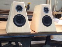
Working on speakers lately, when i have some free time. Got a Funny FE ready for the BA output. Gonna see if it has same magic. Will be using TOshibas from BA3 for gain devices. Toying with alternate buffers as an option. Balanced of course. My output has extra resistors on one rail as well. Too far behind the curve for the active version, at the moment.
First of all thanks Andrew and 6L6 for the answers.
Maybe it is better if I specify that I plan to make a 6 deep complimentary, biased at 3A x channel, 32V rails. I also plan to carefully match the MOSFETs at their operating point, and source resistors too (I remember an article from EUVL...). If reducing the source resistors value to, let's say, 0.47 Ohm can increase a little bit output power (how much?) keeping the circuit stable, why not? But my lack of both technical and practical experience on this subject makes me wonder up to which point it is safe or not...
Regarding this old answer: I have a bunch of 2SK170 and 2SJ74 bought from Spencer, but I can't do any Idss matching. Since I want to use them, I have two options: carefully measure them (recreating somehow Singapore room temperature ), order to Spencer exact matching values and hoping for the best; or see if in my small stock I can find couples good to do the degeneration trick (I remember another EUVL article...). Could this be a valid option?
Third option would be buying matched JFETs from Spencer, but my stock will remain unused...
Any advice is really appreciated.
P.S.: I finally upgraded to my new Maggies 2.7; they are really asking for a new amplifier
Maybe it is better if I specify that I plan to make a 6 deep complimentary, biased at 3A x channel, 32V rails. I also plan to carefully match the MOSFETs at their operating point, and source resistors too (I remember an article from EUVL...). If reducing the source resistors value to, let's say, 0.47 Ohm can increase a little bit output power (how much?) keeping the circuit stable, why not? But my lack of both technical and practical experience on this subject makes me wonder up to which point it is safe or not...
Buy matched Jfets from Spencer, (fetaudio.com) P3 is not there to fix a mismatch - it's a harmonic distortion altering tool.
The Mosfets in the front-end do not need to be matched, as the bias pots will help set everything correctly, but that mechanism is predicated on the Jfets having similar Idss.
Regarding this old answer: I have a bunch of 2SK170 and 2SJ74 bought from Spencer, but I can't do any Idss matching. Since I want to use them, I have two options: carefully measure them (recreating somehow Singapore room temperature
), order to Spencer exact matching values and hoping for the best; or see if in my small stock I can find couples good to do the degeneration trick (I remember another EUVL article...). Could this be a valid option?Third option would be buying matched JFETs from Spencer, but my stock will remain unused...
Any advice is really appreciated.
P.S.: I finally upgraded to my new Maggies 2.7; they are really asking for a new amplifier
Maybe it is better if I specify that I plan to make a 6 deep complimentary, biased at 3A x channel, 32V rails. I also plan to carefully match the MOSFETs at their operating point, and source resistors too (I remember an article from EUVL...).
Good.
If reducing the source resistors value to, let's say, 0.47 Ohm can increase a little bit output power (how much?) keeping the circuit stable, why not?
Because 6-deep was designed for 1Ohm source resistors.
Regarding this old answer: I have a bunch of 2SK170 and 2SJ74 bought from Spencer, but I can't do any Idss matching.
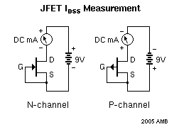
Do you have DMM and 9V battery? If yes, then you can Idss match.
Tempature in Singapore is completely irrelevant, as all you Jfets will be at the same room temperature, yours. Keep the Jfets in the rig for the same amount of time, I usually count to 7 and take reading then.
Since I want to use them, I have two options: carefully measure them.
Yep. Idss measurement shown above.
Third option would be buying matched JFETs from Spencer, but my stock will remain unused...
Might as well do that anyway, keep them for your next project, they are just going to get more expensive...
P.S.: I finally upgraded to my new Maggies 2.7; they are really asking for a new amplifier
6-deep BA-3 will be a great choice for Magneplanar.
Thank you Jim!
Regarding JFETs matching: sorry for my poor English. I'm able to measure Idss (actually I use a regulated 10V psu), but in my stock I can't find matching 2SJ74 and 2SK170.
What I might find (I don't have them at hand right now) are 2SK170 and 2SJ74 with different Idss that are suitable for "EUVL's degeneration trick" ( http://www.diyaudio.rs/index.php?app=core&module=attach§ion=attach&attach_id=13749 ), obviously using Idss (2SJ74) = Id * (1 + Rs*Yfs). I was wondering if this approach could be used here too. In this way I will be able to use every piece of my stock.
I hope it's clearer now
The Singapore temperature thing: if I measure Idss of my JFETs with the same condition in which Spencer measures his (room temperature and 10Vdc), and then I order from him JFET with matching values, maybe I can hope to come up with actually matched pairs. I hope this is clearer too, sorry again for my English (and for my ideas)
Regarding JFETs matching: sorry for my poor English. I'm able to measure Idss (actually I use a regulated 10V psu), but in my stock I can't find matching 2SJ74 and 2SK170.
What I might find (I don't have them at hand right now) are 2SK170 and 2SJ74 with different Idss that are suitable for "EUVL's degeneration trick" ( http://www.diyaudio.rs/index.php?app=core&module=attach§ion=attach&attach_id=13749 ), obviously using Idss (2SJ74) = Id * (1 + Rs*Yfs). I was wondering if this approach could be used here too. In this way I will be able to use every piece of my stock.
I hope it's clearer now
The Singapore temperature thing: if I measure Idss of my JFETs with the same condition in which Spencer measures his (room temperature and 10Vdc), and then I order from him JFET with matching values, maybe I can hope to come up with actually matched pairs. I hope this is clearer too, sorry again for my English (and for my ideas
)
Last edited:
Thank you Jim!
Regarding JFETs matching: sorry for my poor English. I'm able to measure Idss (actually I use a regulated 10V psu), but in my stock I can't find matching 2SJ74 and 2SK170.
What I might find (I don't have them at hand right now) are 2SK170 and 2SJ74 with different Idss that are suitable for "EUVL's degeneration trick" ( http://www.diyaudio.rs/index.php?app=core&module=attach§ion=attach&attach_id=13749 ), obviously using Idss (2SJ74) = Id * (1 + Rs*Yfs). I was wondering if this approach could be used here too. In this way I will be able to use every piece of my stock.
I hope it's clearer now
The Singapore temperature thing: if I measure Idss of my JFETs with the same condition in which Spencer measures his (room temperature and 10Vdc), and then I order from him JFET with matching values, maybe I can hope to come up with actually matched pairs. I hope this is clearer too, sorry again for my English (and for my ideas
Ok, I managed to find matching 2SK170 and 2SJ74 below 0.7% at 10Vdc. The first couple is at 11mA, the other one around 9mA. I don't think there will be problems in having different front end channels.
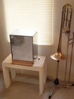
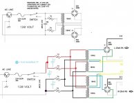
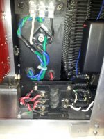
This build has been running without a C9 cap (ghosted blue). Instead of just asking where to place it (them), I drew out the circuit so any additional suggestion could be added. The CL-60s run very hot which I believe is normal, but not sure they are in the best location.
So how many C9s and where?
So how many C9s and where?
Attachments
Last edited:

My fingers are just fine - thank you! As for the brain part, remember I lived through the "60s" so I'm working mostly with cinders there.
My thought was the CL-60s should cool somewhat after the resistance falls, but they stay right up there. I won't fret about it.
Andrew - your idea sounds slick, but I believe would require an additional power source - correct?
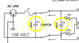
No mention of the C9 filtering. Does that imply it may be considered optional and required on noisy mains only? I see there are two in the BA-1 PS schematic:
"Capacitors C1 and C2 are line-rated types only, as they will be filtering AC line voltages."
My thought was the CL-60s should cool somewhat after the resistance falls, but they stay right up there. I won't fret about it.
Andrew - your idea sounds slick, but I believe would require an additional power source - correct?
No mention of the C9 filtering. Does that imply it may be considered optional and required on noisy mains only? I see there are two in the BA-1 PS schematic:
"Capacitors C1 and C2 are line-rated types only, as they will be filtering AC line voltages."
Attachments
Last edited:
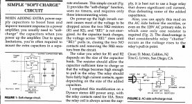
Andrew - your idea sounds slick, but I believe would require an additional power source - correct?
Not if you use an AC relay. Look at the attached soft-start circuits.
Attachments
same talk - last few posts :
http://www.diyaudio.com/forums/pass-labs/241729-aleph-j-illustrated-build-guide-39.html#post3879616
http://www.diyaudio.com/forums/pass-labs/241729-aleph-j-illustrated-build-guide-39.html#post3879616
- Home
- Amplifiers
- Pass Labs
- Burning Amp BA-3