
OK, thanks. Can you explain which components are in the CSS circuit (or point me to a resource to read) ? I've been looking at the OB schematic in this article but don't have the savvy to pull the info I need.
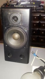
EDIT: I have $3 home brew bench speakers for all testing. But thanks for the warning.
EDIT: I have $3 home brew bench speakers for all testing. But thanks for the warning.
Attachments
Last edited:
if you hard bias lower group (without modulation) , while biasing in same amount but also modulating upper one - that's SE power follower
easiest way is to play some in any graphic proggie and make overal schmtc of one channel ....... to give us (at least to me , I'm thinking in pictures ) proper playground
easiest way is to play some in any graphic proggie and make overal schmtc of one channel ....... to give us (at least to me , I'm thinking in pictures ) proper playground
Don't know if this is the level you need, but this is what I have now and what worked fine for many weeks.
A reminder - the problems started when I took the amp apart for chassis work. At that time I decided to try all mica pads one last time. They failed and the output fets overheated. Power was applied for ~ 10 seconds. All the fets tested good off-board, but some damage may have occurred in other places.
And yes, I bit the bullet and ordered a set of red pads $$$ from the store.
Attachments
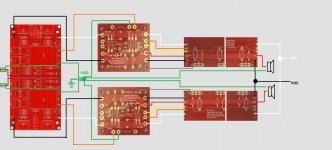
My bad. I truncated the output boards for space on the diagram. Should have used a ziggy line. ") Please see post #1559 for the actual layout.
Please see post #1559 for the actual layout.
"if you want the 'full' 6/pair per channel you actually need 2 of the PCB and daisy-chain them together."
That's the configuration I was using and will return to when these bugs are resolved.
Please see post #1559 for the actual layout."if you want the 'full' 6/pair per channel you actually need 2 of the PCB and daisy-chain them together."
That's the configuration I was using and will return to when these bugs are resolved.
Last edited:
Any chance of a cascode pcb version in the store in order to apply higher voltage in the input jfets?
Thanks
Let me refrase does any one have made an cascode pcb version of the BA-3.
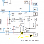
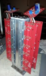
All's well in the kingdom again !. The culprit was a bad Q204 on the bias board. As reported, no mosfet to sink continuity showed up till that last wire (V-) was attached between the bias and output boards. The pic shows the link.
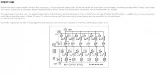
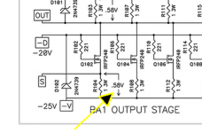
Also, after a loonngg phone conversation with Mr. 6 (who graciously schooled me by walking through all three schematics) the higher reading (.58 V) on the alternating mosfets is due to the output/CCS layout on the board. Had to go way back to the BA-1 article to see the SE schematic.
Both channels now respond properly (0.00 - 3+mV) to trimmer adjustments on the output mosfets. The second pair of output boards will be put back in this evening, and hopefully there will be more good news in the morning.
Great learning experience - thanks all.
Jim, you're a champ !
Attachments
Last edited:

Bob -- Fantastic news! I'm glad you could determine what was the bad component.
I've driven an F4 with a BA-3 front-end as a preamp, which is 99% a BA-3 complimentary. It's a very similar sound, as the follower output stage is almost completely invisible, and the BA-3 FE is strongly related to the F5... But the BA-3 is smoother and prettier without any loss of detail, and can run a lower-impedance load with ease. The F5 is a great amp, I've built no less than 3, and think it's a fantastic project that anybody interested should do, as you will love it.
If you are willing to take on the (not insignificant) extra complication of the BA-3, I think it's worth it.
Anyone compared the sound of BA-3 t an F5?
I've driven an F4 with a BA-3 front-end as a preamp, which is 99% a BA-3 complimentary. It's a very similar sound, as the follower output stage is almost completely invisible, and the BA-3 FE is strongly related to the F5... But the BA-3 is smoother and prettier without any loss of detail, and can run a lower-impedance load with ease. The F5 is a great amp, I've built no less than 3, and think it's a fantastic project that anybody interested should do, as you will love it.
If you are willing to take on the (not insignificant) extra complication of the BA-3, I think it's worth it.
Last edited:
Still Tuning !!
I've been able to adjust to 0.000 VDC across R13 on the front end - and 0.000 VDC offset on the output boards. Those appear stable after about 15 minutes. The only discrepancy is source resistors at 0.6 - 0.61 mV instead of 0.58 (nothing below .58 so far) as called out on the SE schematic. Is that close enough or should I try further adjustments?
Readings across R10 & R11 on the front end range between 0.9 - 1.1 volts.
Great - Have to give you your props as your advice to ignore the many suggestions and just shoot for the zeros brought it home.
Another point of confusion were the multiple tips to find 0.2 mv somewhere on the output boards. A closer look at the schematic (BA-1 article) shows ALL the mosfets have a tie to a 0.58 bus on the SE board.
Point of humor - The first sound test produce a horrible hum.

 Was just a loose plug on the Walkman I use for bench tests.
@6L6 - I'll try but this is the closest I've come to generating an worry ulcer. The output levels are much better with proper voltages - funny how that works
Another point of confusion were the multiple tips to find 0.2 mv somewhere on the output boards. A closer look at the schematic (BA-1 article) shows ALL the mosfets have a tie to a 0.58 bus on the SE board.
Point of humor - The first sound test produce a horrible hum.
Was just a loose plug on the Walkman I use for bench tests.@6L6 - I'll try but this is the closest I've come to generating an worry ulcer. The output levels are much better with proper voltages - funny how that works
- Home
- Amplifiers
- Pass Labs
- Burning Amp BA-3