I'm being a little dense also. 
I have the BA-3 FE boards ready to go, but the initial adjustment procedure from 6L6 refers to the R10 & R11 resistors. Is that on the FE before the output boards are attached , which also have an R10 & R11.
I ask thinking there must be some influence on this FE adjustment when the bias boards and output boards are in the circuit. I've completed the same adjustments on the F5 successfully a couple times, but can't determine if I need the whole package when doing it on this build. What is the sequence?

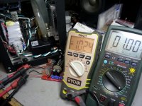
Ah Ha! Made it to first base.
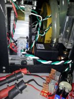
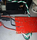
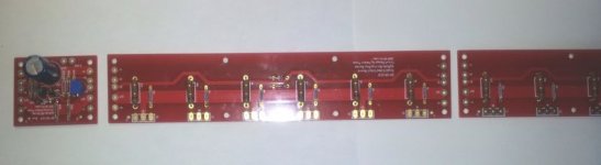
All the trimmers are functional without that nasty green smoke. Due to my handy-dandy home-made heat sinks I had to add some extensions to reach the resistors. I didn't want to buy the Audyn Plus caps for C3 yet, so I have to steal one from an old crossover to get the twin for this one - in the morning.
Haven't decided stereo, dual mono or mono-block yet so I used the F5 PS for the power feed.
Thanks all for the assists.
All the trimmers are functional without that nasty green smoke.
Due to my handy-dandy home-made heat sinks I had to add some extensions to reach the resistors. I didn't want to buy the Audyn Plus caps for C3 yet, so I have to steal one from an old crossover to get the twin for this one - in the morning. Haven't decided stereo, dual mono or mono-block yet so I used the F5 PS for the power feed.
Thanks all for the assists.
Attachments
Now that's what I call a clear definition - thanks. So for a single output board having an S pad on both ends is for convenience/flexability, correct? If I add a second output board to each channel, do I need some sort of "S" continuity between those to feed back to the bias board?
Both ends is for conveniance, right.
Connecting one more board.....hm, hm, .....I have the impression the S point feels only the voltage at one resistor and adjusts the current accordingly for all the other pairs without any more connection....but
I am not quite sure in this case.....logical thinking is often difficult for me....
Andrew T. are you here....?
Connecting one more board.....hm, hm, .....I have the impression the S point feels only the voltage at one resistor and adjusts the current accordingly for all the other pairs without any more connection....but
I am not quite sure in this case.....logical thinking is often difficult for me....
Andrew T. are you here....
?
was it so alogical?
there is the S connection in BA-1 controlling the bias....
and he wants to use not only one outputboard but two...
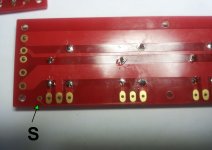
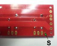
both outputboards show the S pin on both sides and he asks if is it enough to connect one of the S pins of the first output board and must the S pin of the second board also connected to the S pin of the first board....?
really difficult without pictures I understand .....
I looked for the pictures at the shop, but the quality is so bad you can not see the S pin.....
there is the S connection in BA-1 controlling the bias....
and he wants to use not only one outputboard but two...
both outputboards show the S pin on both sides and he asks if is it enough to connect one of the S pins of the first output board and must the S pin of the second board also connected to the S pin of the first board....?
really difficult without pictures I understand .....
I looked for the pictures at the shop, but the quality is so bad you can not see the S pin.....
Attachments
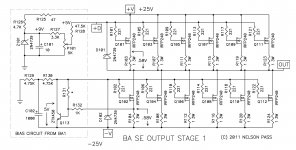
If a second output board (six additional power transistors) is added in series, is there a need to connect the "S" pads between those two output boards. Or is sensing only the first resistor on the OB closest to the bias board sufficient?
Attachments
Last edited:
No need to connect the "S" pads together. The bias circuit is only looking at the voltage drop across that one resistor to control how much the bottom set of power transistors are conducting. The important thing is that all of those are well matched of course so that they share the current equally.
This is a beast of an amp regarding heat dissipation, remember you can easily dial in the amount of idle current by the value of R131 if needed as stated in the article. I forgot what I ended up with there, 30k or something, lower value=less current/heat.
This is a beast of an amp regarding heat dissipation, remember you can easily dial in the amount of idle current by the value of R131 if needed as stated in the article. I forgot what I ended up with there, 30k or something, lower value=less current/heat.
Last edited:
Thanks William, that keeps wiring simple. I didn't match the power transistors but I did get a matched set from buzz for the front end. If I like the sound I'll be happy to circle back and upgrade as necessary. My plan is to get the amp operational as stereo first, and then add the second output boards after I get a feel for what's happening.
The heat management is at the core of this build and will be interesting indeed.
evanc, I have no frame of reference for the power/slp, but my long standing curiosity will soon be answered. Should I be scared 
The heat management is at the core of this build and will be interesting indeed.
evanc, I have no frame of reference for the power/slp, but my long standing curiosity will soon be answered. Should I be scared
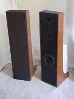
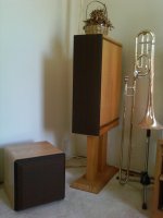
My mains currently are the Sunflowers, a bit on the low efficiency side. The second pair is my DIY 15 year standard that has two Vifa 6.5" and a Morel MDT 30 tweeter in MTM. Crossovers done on Leap system by Masisound. They can play REALLY loud and handle a lot of power with a very nice presentation. Both will probably be overpowered but one always needs an excuse to build something new.
Attachments
Last edited:
Yes, but it does rely on adequate matching of semiconductor devices and resistor devices.
If one wants to check the current imbalances of the output stage semiconductors, then the resistors MUST be matched to far better than the tolerance you expect of the semiconductors
Aim for better than 1% range of resistor values (+-0.5%) and preferably +-0.2%.
If one wants to check the current imbalances of the output stage semiconductors, then the resistors MUST be matched to far better than the tolerance you expect of the semiconductors
Aim for better than 1% range of resistor values (+-0.5%) and preferably +-0.2%.
- Home
- Amplifiers
- Pass Labs
- Burning Amp BA-3