@buzforb 
at the moment I use crippled F4, and with only one output pair,
of course the next days i will try F4 with three and BA-2 with three stages...
But must i really do both F4 and B-2, they are so similar
or do I not see some difference?
I find F5 is a very precise dynamic and detailed amp, I had acoustic effects I had with no other FW amp, for instance sound hitting in the air before the speakers.....
my problem was I came from Accuphase and wanted a more relaxed and tubelike sound,
so I like more F4 and J2 clones and so on.....
I was asking because I have F4 boards and can't decide whether to make them standard or like BA-outputs. The BA amps have more degeneration than the F4 with 1R at source and F4 with .23R, according to Cvillers schematic. Clearly BA is F4 minus the FE, but other things have been changed and it makes me wonder why

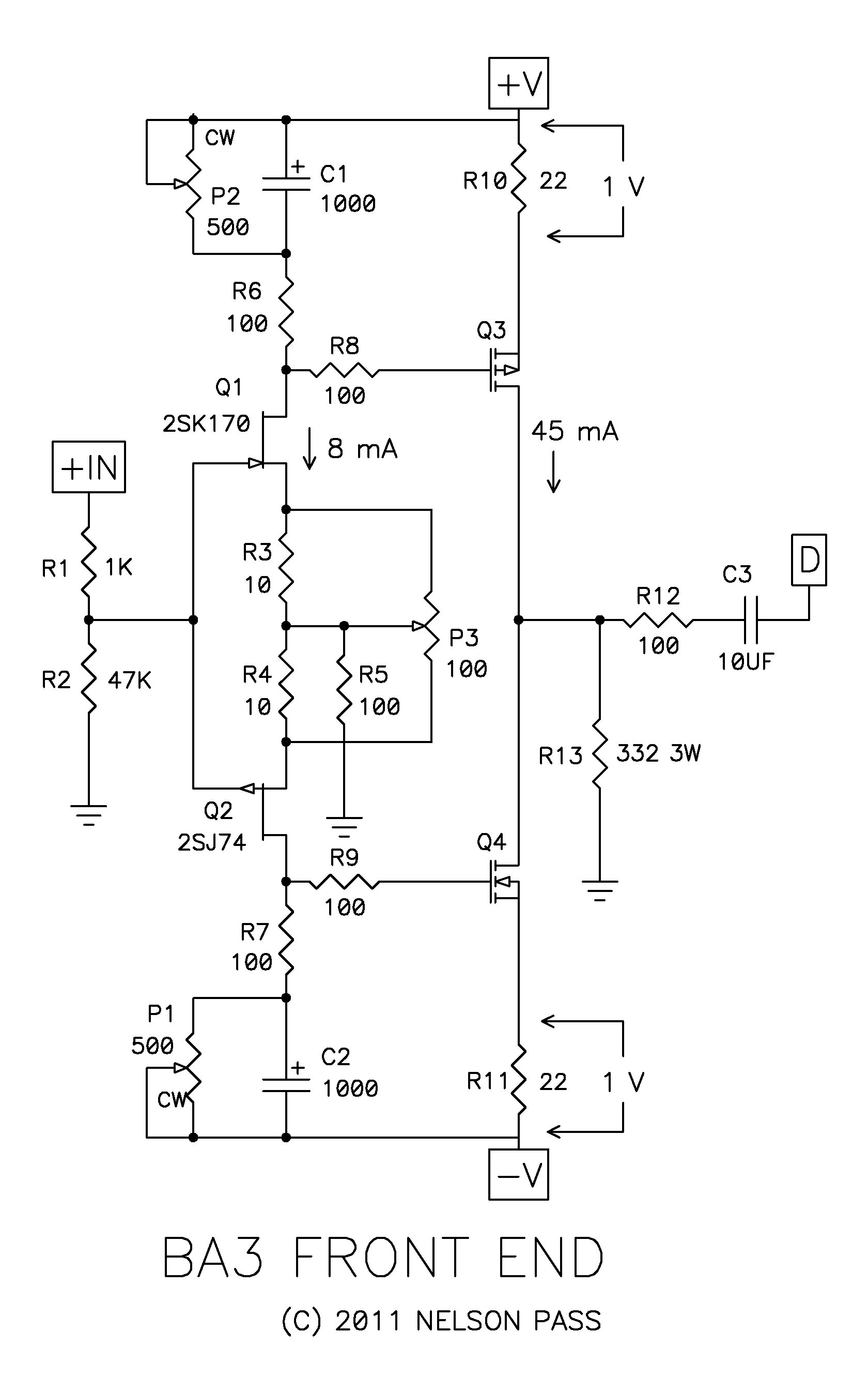
P3 alignment
Hi Guy’s,
I fired up the BA-3 and it sounds great! I do have a question about the distortion adjustment of P3. I had minimized the second harmonic with P3 before I attached the follower output stage, when it was attached I played with P3 and found I could still reduce the additional second harmonic from the follower stage further with P3. So my question is, is it OK to cancel some of the overall amplifier second harmonic by generating opposite phase second harmonic in the first stage? Just throwing it out there.
I also did some distortion testing and could get a THD of .0041, effectively removing all the even order components just leaving the odd. Once you find the Null you can just rock the pot back and forth to watch the spectrum change. FUN!
I’m using ARTA and the Cordell Distortion Magnifier and it works great!
Thanks generg,
Can you find this Null point without a distortion analyser? In other words if one achieves the 1V across R10 and R11 by altering P1 and P2 do we have a null point?
Chris
Thanks generg,
Can you find this Null point without a distortion analyser? In other words if one achieves the 1V across R10 and R11 by altering P1 and P2 do we have a null point?
Chris
For years I have been using an oscilloscope to look at the waveforms and I can tell you I can’t see the distortion in the wave forms at that level of distortion. With a laptop and the DM I can see it so easily that I wonder how I got by without it. A laptop and a couple of hundred dollars to buy the DM kit is well worth the price. So in a word, no.
Botte, what product are you using? I am in the market. Thanks.
I'm using ARTA in the spectrum analyzer mode on a PC laptop. The built in sound card has a THD of .008 in loop back, so using the DM I can measure down to .00008 or 40 dB lower. That's low enough!
See ARTA
The joy of bringing k2 to zero is very good......
Later you remark......
- How stable is the point after closing the case and all heating up?
- the zero point is only for one position of the volume pot. Mine is direct coupled to the input, when I change from lower to a louder signal the mixture of K2 to K3 changes.
- k2 has a maximum with a position at 5 o'clock and goes down again at full volume.
- maybe it is useful to minimize k2 in the region I am normally hearing.
- maybe it is better to have a coupling cap, so the pot not interacts directly with 74/170
- I was not very successful to reduce the distortion of input and output stage combined like Botte did.
- I will treat output stage separately
My pot is a 10k pot, might a higher value less influence the J74/K170 combo? Even the offset changes in a small amount when I change the volume....
O.k. Life is more complicated than thought in the beginning......
We are used to......
The joy of bringing k2 to zero is very good......
Later you remark......
- How stable is the point after closing the case and all heating up?
- the zero point is only for one position of the volume pot. Mine is direct coupled to the input, when I change from lower to a louder signal the mixture of K2 to K3 changes.
- k2 has a maximum with a position at 5 o'clock and goes down again at full volume.
- maybe it is useful to minimize k2 in the region I am normally hearing.
- maybe it is better to have a coupling cap, so the pot not interacts directly with 74/170
- I was not very successful to reduce the distortion of input and output stage combined like Botte did.
- I will treat output stage separately
My pot is a 10k pot, might a higher value less influence the J74/K170 combo? Even the offset changes in a small amount when I change the volume....
O.k. Life is more complicated than thought in the beginning......
We are used to......
I have my source capacitivly coupled to the input of the BA-3, it would seem to me that your potentiometer is raising and lowering the impedance on the input FETs.
I did all my testing at 2.8 volts (8v p-p) output, the input board has lower distortion than the follower and once hooked up I found that the set point for lowest distortion of the second harmonic was different than before I hooked it up. Now this could be the capacitive load from the follower or an interaction with the distortion of the follower, I’m not sure.
By the way, when I adjusted P3 it didn’t change the odd harmonic level, only the even.
The offset and bias are quite stable even in the heat.
I hope this helps.
Last edited:
Hi, Andrej, Q3, Q4 are:
"The 2SJ313 and 2SK2013 are still available, and you can use them or substitute other Mosfets, such as the Fairchild FQP3N30 and FQP3P20. The Vgs of the Toshibas is about 2 volts. Some of the alternatives will be in the region of 4 volts or so, requiring a higher value for P1 and P2, probably 1K ohm."
From N.P. article
By the way, when I adjusted P3 it didn’t change the odd harmonic level, only the even.
The offset and bias are quite stable even in the heat.
I hope this helps.
Can we say that once the 1V across R10 and R11 have been achieved via P1 and P2 then we can adjust and listen to the variations using P3 without going back to adjust P1 and P2 each time?
Chris
Hi, Andrej, Q3, Q4 are:
"The 2SJ313 and 2SK2013 are still available, and you can use them or substitute other Mosfets, such as the Fairchild FQP3N30 and FQP3P20. The Vgs of the Toshibas is about 2 volts. Some of the alternatives will be in the region of 4 volts or so, requiring a higher value for P1 and P2, probably 1K ohm."
From N.P. article
I am ordering some of those.
I might offer a few matched up to sell if JackinnJ does not.
Can we say that once the 1V across R10 and R11 have been achieved via P1 and P2 then we can adjust and listen to the variations using P3 without going back to adjust P1 and P2 each time?
Chris
I was referring to the follower stage. With the input stage all the controls interact but not that bad, so you can spin P3 and watch the change in second harmonic distortion, then just tweak P1 or P2 to restore the DC balance on R13. Once you are in the 50mA range it’s not such a big deal to have them exactly the same it’s the DC across the load R13 you are trying to minimize.
- Home
- Amplifiers
- Pass Labs
- Burning Amp BA-3