Glad to help.
I spent many hours fighting hum. Turned out I had two problems: ground loops, and EMI being coupled into the amp from a dimmer switch that was radiating noise.
The star ground/CL60 isolation scheme fixed everything.
I can't take credit for inventing it though - many others have blazed those trails.
6L6 and Google got me on the right track.
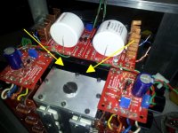
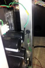
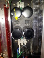
Well - Did you see the amazing disappearing post??  The hum was/is completely gone and that part was excellent. However, one of the resistors on one power supply got so hot it started to glow after ~ 4 minutes. Could well have been a short or bridge from the rework so I'm taking a good look now. I have a new set of resistors if needed as one or more on that side probably fused.
Back to the bench
The hum was/is completely gone and that part was excellent. However, one of the resistors on one power supply got so hot it started to glow after ~ 4 minutes. Could well have been a short or bridge from the rework so I'm taking a good look now. I have a new set of resistors if needed as one or more on that side probably fused.Back to the bench
Attachments
Last edited:


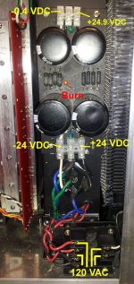
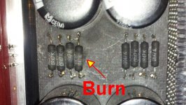
All is well in the kingdom again. Nothing was lost other than the resistors. The grounding scheme is still free of hum and the sound is full and undistorted. Three of the resistors show nothing for ohms or continuity. The fourth reads 14.7 Mohms (should be 47K) so it was probably about to fry also.
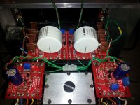
I found no major errors in the wiring other than some shabby soldering, but as I said the amp has functioned fine for months. There was one small loose blob of solder under the front end, but the gap between the top of the transformer cage and the bottom of the front end PCB is a full 1/4".
Does anyone have a suggestion on what could have pushed that much energy back or toward the PS resistors? It seems to me that something else should have died with that much of a fault.
Not sure what is normal but I get this after ~ 50 minutes at 90% volume with the bench speakers:
Resistors (4 piece avg.)
R - = 45 C / R + = 39 C
L - = 44 C / L + = 44 C
Water Box = 32 C
Output Transistors = 29 C - 32 C
Ambient = 21 C
I'll hook the low efficiency Sunflower speakers up this afternoon to see if that makes any difference.
I found no major errors in the wiring other than some shabby soldering,
but as I said the amp has functioned fine for months. There was one small loose blob of solder under the front end, but the gap between the top of the transformer cage and the bottom of the front end PCB is a full 1/4". Does anyone have a suggestion on what could have pushed that much energy back or toward the PS resistors? It seems to me that something else should have died with that much of a fault.
Not sure what is normal but I get this after ~ 50 minutes at 90% volume with the bench speakers:
Resistors (4 piece avg.)
R - = 45 C / R + = 39 C
L - = 44 C / L + = 44 C
Water Box = 32 C
Output Transistors = 29 C - 32 C
Ambient = 21 C
I'll hook the low efficiency Sunflower speakers up this afternoon to see if that makes any difference.
Last edited:
Just an observation. When dealing with power resistors I always space them up off of the board to allow for circulation. Mounting in close proximity to other hot running resistors or devices will derate them also. You can use simple ohm's law to calculate the power being dissipated in each resistor while in operation (I=E/R then P=I*E).
I got a couple messages about the " (should be 47K)" in my post #1488. The correct value is 0.47R - 1R (as in posted BOM) and that is what I have installed. Just took a lazy look at the resistor as I posted and interpreted the "K" incorrectly. Sorry if I caused some confusion.
Attachments
New BA-3 build
Hi,
like 6L6 suggested, for my Maggies I'm going to build a BA-3 with complementary output.
I would like to share some of the choices that I made for this new project:
- PSU: I have a 800VA 2x24V transformer. At the moment I plan a simple CRC filtering. I will make some simulations with PSUD2 to see the price/benefit of other configurations.
- Chassis: I will build it with spare aluminum plates, with the following 300mm high heatsinks:
PRODOTTI - Meccal - Dissipatori Estrusi - Extruded Heat sinks
I will use two of them per side, and I expect about 200W dissipation capacity per channel with 25*C ambient temperature (it will be a winter/mid-season amp )
- Front-End: I will use the big +/-32V PSU (same for the output stage). Here I accept suggestions: should I make a dedicated one? I also do like the possibility to switch the front end with other designs, so maybe I can treat the front-end like a preamp, and put it in another enclosure. Suggestions?
- Output stage: I will use 6 pairs per channel. With those heatsinks they should be biased at 3A max per channel. Is the transformer VA rating enough?
Is everything good to your eyes?
Then I have a final question. P3 on the frontend can be used to compensate some mismatch between the JFETs. Has anyone some indication on how much is this "some mismatch"?
Thanks to this wonderful community and expecially to Nelson. One of these days (better say, months...) I will post some pictures of my completed projects.
Giulio
Hi,
like 6L6 suggested, for my Maggies I'm going to build a BA-3 with complementary output.
I would like to share some of the choices that I made for this new project:
- PSU: I have a 800VA 2x24V transformer. At the moment I plan a simple CRC filtering. I will make some simulations with PSUD2 to see the price/benefit of other configurations.
- Chassis: I will build it with spare aluminum plates, with the following 300mm high heatsinks:
PRODOTTI - Meccal - Dissipatori Estrusi - Extruded Heat sinks
I will use two of them per side, and I expect about 200W dissipation capacity per channel with 25*C ambient temperature (it will be a winter/mid-season amp
)- Front-End: I will use the big +/-32V PSU (same for the output stage). Here I accept suggestions: should I make a dedicated one? I also do like the possibility to switch the front end with other designs, so maybe I can treat the front-end like a preamp, and put it in another enclosure. Suggestions?
- Output stage: I will use 6 pairs per channel. With those heatsinks they should be biased at 3A max per channel. Is the transformer VA rating enough?
Is everything good to your eyes?
Then I have a final question. P3 on the frontend can be used to compensate some mismatch between the JFETs. Has anyone some indication on how much is this "some mismatch"?
Thanks to this wonderful community and expecially to Nelson. One of these days (better say, months...
) I will post some pictures of my completed projects.Giulio
12 output transistors per channel?! Why so many? It may be tricky getting so many pairs matched to each other. Why not use 2 pairs per channel and bias them higher? I suggest it's not the total bias current that matters to drive down distortion, but the bias per device...- Output stage: I will use 6 pairs per channel. With those heatsinks they should be biased at 3A max per channel. Is the transformer VA rating enough?
Is everything good to your eyes?
2 pair a channel will not have anywhere near the current capability necessary for Magnepans.
Yes, fewer devices at higher bias will get the 'bias magic' sooner, but you still need to think about current capability... Talking to Wayne and Nelson both, it seems that 3 pair/channel is about the minimum that would really deliver the goods.
Where the sweet spot really starts to sing on the BA- amps is with higher rail voltage. 32v seems to be ideal.
Yes, fewer devices at higher bias will get the 'bias magic' sooner, but you still need to think about current capability... Talking to Wayne and Nelson both, it seems that 3 pair/channel is about the minimum that would really deliver the goods.
Where the sweet spot really starts to sing on the BA- amps is with higher rail voltage.
32v seems to be ideal.the 800VA 24+24Vac transformer has a maximum continuous DC current rating of 8.3Adc.......... PSU: I have a 800VA 2x24V transformer. ...............
- Output stage: I will use 6 pairs per channel. With those heatsinks they should be biased at 3A max per channel. Is the transformer VA rating enough?
.........
One channel @ 3A output bias uses only 36% of the rating. It will stay cool to warm.
Two channels each biased to 3A will use 72% of the rating. It will run hot.
Will you run any of your other components @ 72% of their maximum rating, continuously?
the 800VA 24+24Vac transformer has a maximum continuous DC current rating of 8.3Adc
Hi Andrew, I can't figure how you came to this value.
24+24Vac results in ~+-32Vdc.
8.3Adc @ +-32Vdc is equivalent to a continuous maximum output of 533Watts.
The transformer is 800VA. Apply the manufacturer's de-rating factor for a capacitor input filter. Usually it's around 0.7
800 * 0.7 = 560
560 is the maximum continuous output after the capacitor input filter.
But you have the losses through the bridge rectifier. That another 1.4V * 8.3A = 11.6 Watts leaving 548 watts. that's less than a 3% error.
Take the AC current rating.
For a capacitor input filter allow HALF for the continuous DC rating.
I'll guess and say I have explained this around a dozens times before.
Last edited:
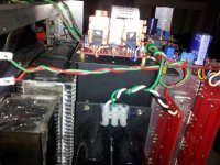
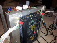
Andrew, I've been using two 500VA in a dual mono configuration with the same number of output devices as giuliodido plans to use. Do you think that's sufficient according to your/the formula? The amp is liquid cooled but I have never noticed any heat rise on the transformers.
BTW - tried all mica again yesterday with disastrous results. After three tries I simply don't have the touch for that style of insulators. For me - the cost savings is just not worth the heartache.
BTW - tried all mica again yesterday with disastrous results. After three tries I simply don't have the touch for that style of insulators. For me - the cost savings is just not worth the heartache.
bcmbob, I think it depends on the secondary voltage and the bias you set, and not on the number of devices used.
Andrew, thank you for the explanation. I tried to search for some more detailed information on the net, but it seems I can't find anything good. Do you have any other useful source I can examine?
Andrew, thank you for the explanation. I tried to search for some more detailed information on the net, but it seems I can't find anything good. Do you have any other useful source I can examine?
Last edited:
- Home
- Amplifiers
- Pass Labs
- Burning Amp BA-3