I've just put together a BA-3 front end. Using it to push a F5…I have a 25K pot in front of it. I am using matched BL grade jets with fairchild mosfets.
I am a bit surprised by the gain or lack there of. This is supposed to be a 30DB gain stage…I am getting less gain than my jfet boz (around 20 db). I am guessing the BA-3 FE is producing about 10-15DB gain. I have not measured it…I am just guessing. But I know it's not 30db.
Looking back at past posts others have estimated the gain of the BA-3 FE at around 10X. So what's the deal? Is it 30db or not?
P.S. I am happy with the BA-3 FE. Sounds great, have yet to play w/P3. Gain is sufficient for my needs.
Attachments
Papa is often giving us spoon soaked in honey ........ with some mustard beneath 
gain around 11x (21db-ish) is more realistic figure then 31x (30db-ish)
increase Jfet drain resistors to 270R and you'll have ~30db
of course - re-bias to have intended Iq through outputs
gain around 11x (21db-ish) is more realistic figure then 31x (30db-ish)
increase Jfet drain resistors to 270R and you'll have ~30db
of course - re-bias to have intended Iq through outputs
Last edited:
Dear Zen Mode are you referring to R6 & R7 ?Papa is often giving us spoon soaked in honey ........ with some mustard beneath
gain around 11x (21db-ish) is more realistic figure then 31x (30db-ish)
increase Jfet drain resistors to 270R and you'll have ~30db
of course - re-bias to have intended Iq through outputs
Q1 and Q2 are the input JFETs. They are set very close to unity gain.
Q3 and Q4 are the output MOSFETs. They are in push-pull. The gain is R13/R10 plus R13/R11.
Stock values of R10 and R11 are 22 ohms. Stock value of R13 is 332 ohms.
332/22 + 332/22 = 15.1 + 15.1 = 30.2
Voltage gain in db = 20*log(30.2) = 29.6 db
Q3 and Q4 are the output MOSFETs. They are in push-pull. The gain is R13/R10 plus R13/R11.
Stock values of R10 and R11 are 22 ohms. Stock value of R13 is 332 ohms.
332/22 + 332/22 = 15.1 + 15.1 = 30.2
Voltage gain in db = 20*log(30.2) = 29.6 db
Blivit Line Stage, Phase 1
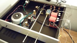
In my search for ever louder music, I decided to build a low-gain line stage for use with the BA-3.
Phase one of the effort is attached. I wanted the wiring to be pretty, but I spent the last 17 man years (or so it seemed) troubleshooting a dead channel. Turned out it was a bad solder joint on one of the RCA input jacks - how boring and difficult to find! Anyway, the wiring WAS nicely done, by my standards, before I tore the damn thing apart trying to fix it.
I got so excited when it made stereo music I just had to post it. (I promise in phase 2 I will make it pretty).
Power transformer: Antek 18V 100VA
Power supply: Broskie B-PS-1 bipolar regulator set at +/- 21 VDC
Voltage Amp: BA3 front end set with a gain of about five (13 db or so)
Volume control: a 50K pot I found in the parts box, in a shunt config with a 47K resistor.
Enclosure: Galaxy 288 chassis
After you cram everything in, it's a blivit. (If you don't know, Google it......)
The thing is dead quiet, using the standard star ground and CL60 technique. (Yes, I was surprised too. I was worried the blivit architecture would be an issue, but it's not).
BTW: To paraphrase others, it sounds neato buffo. (Remember I may not be objective).
Next step is to clean things up, use a better volume pot, fancier knob, etc. I will keep you posted. I will most likely start that on Thursday, while suffering from a hangover. Solder fumes seem to help.
Cheers and Happy New Year.
Attachments
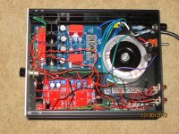
I'm having problems connecting a new DAC to the BA-3 build. A hum/Gnd loop appears with either the USB shield and/or the S/PDIF ground connected. This is what I found:
1. The DAC is hum free with BrianGT monoblocks. (full metal chassis)
2. No hum with one MyRef LM3886 build in metal chassis.
3. Hum with a different MyRef build on wood test base.
4. BA-3 operates hum free with battery power (Walkman/phone)
5. BA-3 operated hum free with optical attached to DAC.
6. Earth ground from DAC power cable to BA-3 chassis - no hum reduction.
7. USB and/or BNC shield to BA-3 chassis - no hum reduction.
So I'm baffled. I've considered an isolation transformer somewhere along the signal path, but not sure that's the best solution. Not sure if I've made a mistake in the grounding path of the BA-3, but the fact that battery and optical sources are hum free reduces that possibility - I think.
Any Ideas ???
Attachments
Last edited:

I made myself absolutely crazy chasing a hum/buzz problem when I first built the BA3. Here is what worked for me:
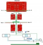
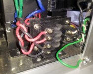
1. Implement a star ground. Tie all the grounds to an isolated barrier strip. Do not daisy chain the grounds. Do NOT tie the AC safety ground to the barrier strip. In the photo I posted above, you can see the barrier strip at the bottom of the photo. I bought mine at Radio Shack, along with shorting clips. Basically what you get is an isolated "star ground" bar with plenty of connections. Once again, this bar must be electrically isolated from the chassis.
2. Isolate the RCA inputs and outputs from the chassis.
3. Install another ground bar that shorts to the chassis. (See photo, it's the big silver bus bar.) If the chassis is anodized, sand/scrape down to bare metal for good contact between chassis and ground bar. For the shorting ground bar I used one of these:
Amazon.com: Blue Sea Systems 6 Gang Common 100A Mini Grounding Busbar: Sports & Outdoors
4. Connect the isolated star ground bar to the shorting chassis ground bar using a CL60 thermistor.
5. Connect the AC safety ground (the green wire from the power cord) to the shorting chassis ground bar.
The only connection between the isolated star ground bus bar and shorting chassis ground bus bar should be the CL60. The CL60 gives about 10 ohms of isolation between the two ground bars, which helps prevent ground loops. If there is a fault somewhere in the system, high current will flow through the CL60, which will lower it's resistance and short the fault to safety ground. The only other connection to the shorting ground bar should be the AC safety ground.
Try that and let us now how it works out.
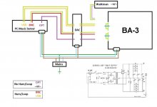
O.K. - here is my interpretation. Each leg of the AC feed already has it's own CL-60 to avoid a soft-start - working so far. 
Not 100% sure about common from power supplies.
Please review/confirm - I'll wait")
Not 100% sure about common from power supplies.
Please review/confirm - I'll wait
Attachments
Last edited:
- Home
- Amplifiers
- Pass Labs
- Burning Amp BA-3