Can this clever control mechanism (P3) be used on a differential pair with similar effectivieness on outcome?
Yes indeed.
-- you can do the same with a LTP such as in the BA-1/2 'consolidated' front end.
I used to have a preamp with tubes, and I biased the feedback triode just a bit off from ground and saw the second harmonic change (increase); very nice sounding effect; I used that because I could not use a trimpot in the common cathode because it was a seven-pin device.
A French audio designer called Héphaïstos wrote about this effect. It just changes the load-line a little bit if I understand it correctly.
As far as I see this is a little different from introducing a small resistance such as a 20 ohm trimpot in the common drains of that FET-LTP. Because then you are trimming the transconductance of the LTP input/feedback jfets, and changing their respective amplification factor in a hefty way that might even introduce higher order harmonics in a very low quantity too (that is just hearsay, I do not have a FFT).
albert
Practical implementation question. If a person were to make a modular front end for the BA Amps, where the output stage is housed in a seperated chassis from the front end, with external lines connecting the two, like a preamp, would there be connection/noise problems? I can invision multiple small inclosures housing different front ends that can plug and play with volume pot in front and output behind.
OK. That is what i thought. What is the advantage to the naked F4 BA-output) over the standard. I know Nelson talks using increased capacitance to clean up the square wave in BA-2. Is this main purpose. I assume the trade-off is the cap needed in signal path for coupling.
Piano fine.....!
New situation with BA-3,
I took it out of the F4 case, put it in my preamplifier case ( Aleph P had to go), made of two aleph p PSU a symmetrical +-24V supply for BA-3, by changing the Zener diodes to 3x 9,1V. Works perfect!
In front of BA-3 I tried Warpspeed and a TKD 2P-2511 Stepped attenuator. Before I had the attenuators between cd-player and BA-3/F4. This worked not so good. The value of the pot, one time 10k and later 100k, interacted clearly with the cables.
When I put the pot before BA-3 as a pre, the output impedance of BA-3 could drive the 1m cable to the F4 much better.
I also tried the F4 with and without the F-fet input stage. Normally I preferred the F4 ( for instance with pumpkin) with the J-FETs, this time the sound was better coupling the BA-3 directly to the crippled output stage.
The sound is now combined with open baffles (Lowther/tone tubby) very unaggressive and very elegant and fluent like water.....
I know these words are not adequate to describe sound, but I do not find better...
It is (again) a different sound world and as Nelson likes to say you can hear your cd collection again all over....
I am really trying to develop a setup where the output stage/F4 is in it's own enclosure. It will have either a dock station for a BA FE or inputs for using the standard F4. There would be a switch toggling between standard F4 FE vs BA setup. Multiple FE would be in small separate enclosures, which when plugged in, could run off F4 rails. If not using BA type FE, you have access to standalone F4 and all it's pleasantries or with out Jfet FE if you so choose. The brilliance of this setup is the fact that it is modular. If you like the output stage, you have a limitless amount of possibilities in front. The fact that you have had success with using the volume control before the BA FE, Generg, is encouraging. We audio addicts need as much versatility as possible.
OK. That is what i thought. What is the advantage to the naked F4 BA-output) over the standard. I know Nelson talks using increased capacitance to clean up the square wave in BA-2. Is this main purpose. I assume the trade-off is the cap needed in signal path for coupling.
The advantage is removal of the Jfet buffer and whatever contribution it
makes. Certainly the naked stage is simpler to build, and the BA-3 is
up to the job of driving it.
just in case ..... schm and part of text , finally in peace

rest of story - still here :
http://www.diyaudio.com/forums/diyaudio-com-articles/194809-burning-amplifier-ba-3-a.html
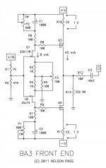
" This is familiar enough. Q1 and Q2 are JFETs which self-bias into resistors R3 and R4 at currents around 8 mA. R1 is chosen to avoid oscillatory interaction with whatever source impedance you might have, and R2 provides a DC reference to ground in the event that the source does not, and also establishes the nominal input impedance.
Q1 and Q2 are largely degenerated by R5, setting the amount of AC current which flows through them for a given input voltage. The voltage gain of this initial stage is approximately
the value of Drain load resistors R6 plus R7 divided by R5. In this case we have roughly unity gain – the Jfets are used as unity gain DC level shifters to Q3 and Q4.
Coming off the Drain of Q1 is the loading network of R6, C1 and P2, and there is a comparable network of R7, C2, and P1 attached to the Drain of Q2. R6 clearly sets the AC load for Q1, but the DC requirements to bias up Mosfet Q3 are higher than that, so P2 in parallel with C1 provides a higher resistance value below about 0.5 Hz, and gives the approximately 3 volt DC drop required to bias the Mosfets.
P1 and P2 are adjusted so as to set the DC bias of Q3 and Q4. You will want to set them at zero when you first fire up the circuit, and increase their resistance to achieve the correct bias voltages across R10 and R11 (about 1 volt) while also keeping the output DC offset voltage at a minimum. This circuit is capacitively coupled at the output, but low offset measured at the Drains of Q3 and Q4 will maximize your output voltage swing.
The voltage appearing at the Gate of Q3 is amplified by something less than the ratio of R13 divided by R10, and with the same happening at Q4(R11) and considering the transconductance of the Mosfets, comes out at about 15. Both of them added make a system voltage gain of about 30X, or 30 dB.
R10 and R11 help set the voltage gain, and they also help stabilize the bias of Q3 and Q4, else it would tend to drift upwards as the parts warm up. The bias current here is about 50 mA, and it will deliver peaks of approximately 100 mA. Q3 and Q4 require heat sinks.
Of course you can bias this circuit higher if you wish – 100 mA bias is perfectly OK as long as you properly heat sink Q3 and Q4, and if you are crazy (like me) you can experiment with higher bias, remembering that the parts are rated at 25 watts, and that it costs you voltage losses across R10 and R11. If you want to play with even higher bias, you can consider lowering the values of R10 and R11 and also R13, all in proportion.
The supply voltage is only critical with respect to the voltage rating of the input JFETs, which are nominally 25 volts. In actual testing, they break down around 40 volts. I wouldn't worry about running them as high as 30V. Hot-rodding this circuit would likely involve cascoding the input Jfets to allow higher voltages. "
rest of story - still here :
http://www.diyaudio.com/forums/diyaudio-com-articles/194809-burning-amplifier-ba-3-a.html
Attachments
he's busy layin' da Red Carpet somewhere at SF Bay
do not be shy, turn around on the carpet
Obviously.
(just think, you may become the 1st Red Carpathian in the Bay)
Attachments

Last edited:
Caps and biasing
For those who don't like electrolytics why not bias the mosfets with a couple of green leds with a 5 Kohm pot across them (one pair for each mosfet connected to each power supply rail). The wiper of each pot could be connected to the mosfet gate by a 100 Kohm resistor. The mosfet gates could then be AC coupled to the 100 ohm jfet drain resistors. 1uF or larger film caps should be used.
This would also leave the distortion trim pot free from influencing the Mosfet
DC bias pot setting and allows fredom from interaction of pot settings.
I have already ordered my PCB board and parts. When Mr. Pass throws something out there that is so different than what everyone else is doing
one must become very curious.
Fred Dieckmann
1st Red Carpathian in the Bay
Surely the most obscure pun of the week......
Last edited:
Loweing the gain a bit?
So what do you guy’s think about cutting the gain down a bit, to about 12.5X or 22dB. We could sub R10 and R11 with 50ohms and increase P1 and P2 to 1K so we can still keep the bias about 50mA. The voltage drop across R10 and R11 would need to be 2.5 volts. We would be wasting output voltage but I was thinking about a regulated supply and running the front end about 5 volts over the output section.
Comments appreciated
Hello Gentlemen,
This is my first post here on the BA.
I ordered the boards, and I am trying to get all needed parts.
One thing that is not specified in the BOM is the mechanical parts: heatsinks and chassis.
I would be interested to know which heatsinks you use (size, K/W, ...) for the BA-1-2-3 power section, and where in Europe I could buy them.
- Home
- Amplifiers
- Pass Labs
- Burning Amp BA-3