
Mica comes in any thickness from 1 and a bit mil to 10mil.Andrew,
Out of curiosity, on another thread you were talking about segmenting micas into thinner layers -difficult to comprehend based on this experience. How did you install those, and were you using something wider than TO-220?
This morning I swapped the front end leads to confirm the channel volume imbalance is coming from it and not the bias or output boards. What adjustments/readings are needed to get that resolved?
For good thermal conductivity you should be using the thinest end of that range.
Hand slicing down to less than 2mil is possible with out too much difficulty.
To less than 1.5mil without breaking cracking the layers is more difficult.
Sometimes I can get 3 <2mil layers from one 6 to 7mil mica. If one breaks I just discard, or keep the bigger piece for smaller devices (To220 or To126).
With good lighting and good eyesight assictance you can see if a layer breaks and leaves a step. This step can sometimes be sliced off to leave a complete unstepped surface.
BUT !!!!!!!
the sink face and the back face of the device MUST be clean and free from burrs. If necessary you can "rub down" the device until the copper shows evenly over the whole area. This removes the higher thermal resistance of the tinned layer. But it must be flat AND clean.
Thanks Andrew, That's quite a process. I'm pretty sure that in my haste I contaminated the mica. Never thought to polish up the fets themselves - good tip.
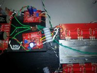
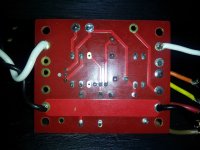
I cleaned up the wiring a bit - but it isn't a very pretty picture. Looks like +6 and - 6 to me.
I cleaned up the wiring a bit - but it isn't a very pretty picture. Looks like +6 and - 6 to me.
Attachments

Last edited:
One remark on Mica insulaters.
The thickness of all Mica insulaters for the electrically insulation of power semiconductor devices on metal heatsinks are specified to 50 microns = 2mil.
At this thickness their heat resistance is 0.4 K/W.
Usually a very thin coating with thermal grease on both sides of the insulater increase the heat conductivity by equalizing the surfaces.
It is not recommended to mechanically thinning the insulaters due to the risk of damage.
The gain of thermal conductivity through thinning is minimal, but the risk of damage and thus creating an electrical short between device and heatsink is very high.
It is mportant before assembling the device with Mica on the haetshink to grind the metal surface around the thread hole to avoid damages on the Mica.
Gerd
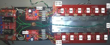
Those readings were from Gnd to each lead of each resistor. These are across the same large 1R brown resistors. Doesn't the first set show I may have burned some of the FETs with the bad mica installations?
Yes, the 3.0 volt bias readings moved when I adjusted for 0.0 VDC at the "OUT" of the output boards.
Yes, the 3.0 volt bias readings moved when I adjusted for 0.0 VDC at the "OUT" of the output boards.
Attachments
Last edited:
Re-measure the 1 ohm resistors on that bottom output board as buzz suggested. Forget about ground, put red probe on one side of the resistor, black on the other. Should be .6 volts or so, but let's see how much variation there is. You determine current through each by simple ohm's law, I=E/R
... starting bias voltage of 3.0 volts, or 4.5 volts, or any other suggested number means nothing. Correct voltage is whatever it takes to get 0V DC offset. The operating current of the output stage is determined by that bias circuit for the bottom set of FET's, which as I said is basically fixed. When you adjust the trimmer, you are turning the top set of FET's on more, or less, so that the current is equal, result is 0 volts DC offset.
... starting bias voltage of 3.0 volts, or 4.5 volts, or any other suggested number means nothing. Correct voltage is whatever it takes to get 0V DC offset. The operating current of the output stage is determined by that bias circuit for the bottom set of FET's, which as I said is basically fixed. When you adjust the trimmer, you are turning the top set of FET's on more, or less, so that the current is equal, result is 0 volts DC offset.
Last edited:
Something is wrong. If those readings are correct you've got nearly 5 amps of current flow. My feeling is something must not be right with that guys bias circuit (for the bottom set of FET's). Are you sure the BJT is healthy and all values are correct, board has no partial shorts, etc...
You guys certainly know your burning amps. 
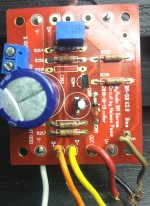
Readings now much better with new part. Still a little more sound coming from the top channel - but the stereo image is just shifted to the left as opposed to the right channel being almost non existent.
Should I do more readings on the front end, or just try to center the image with P1 - P3?
Readings now much better with new part. Still a little more sound coming from the top channel - but the stereo image is just shifted to the left as opposed to the right channel being almost non existent.
Should I do more readings on the front end, or just try to center the image with P1 - P3?
Attachments

Just listen and enjoy for a while. THe current sharing on the bottom fets is not the best. You could try switching them around. Just check them every once in a while to see if it improves. If it were me, and all sounds good, I would just listen for a week. Pick it up again next weekend.
- Home
- Amplifiers
- Pass Labs
- Burning Amp BA-3