If an electrolytic cap is used for C3, is the polarity on the board from the DIYAudio Store correct? The silkscreened polarity shows positive on the D output from the board, but when driving a BA-2 complementary output board the D (input) is at about -4V for zero volt output. Thus I would expect the electrolytic to need the opposite polarity.
Electrician Needed !
Still struggling. Here is what's going on:
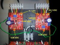
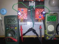
1. +/- 24.5 VDC readings are correct at all pads on all three PCBs.
2. On the front end board - reading across the Gnd and D(Drive) -Red/Grn - wires produces 4.5 VDC.
3. Attaching Gnd/D to terminals (A & B) on top bias board produces 4.5 VDC at both the terminals and at R214 (C).
4. Attaching Gnd/D to terminals (1 & 2) on the bottom board produces 0.0 VDC at the terminals and R214 (3).
5. On the bottom bias board both the transistor (Q204) and the small cap (C209) were replaced with new pieces.
6. Doing a swap, both large caps (C207 -1000 uF) allow the correct 4.5 VDC reading on the top bias board (operating channel) at both the terminals and R214.
All that's left is the zener diode (or possibly a resistor) on the bottom bias board. So does that sound like what a blown diode would do? And of course that's the part I didn't re-order. In my stash I have some 12V-1W and 13V-1.3W zeners but no 9.1V-1W. Can either of the two I have be used along with trimmer adjustments? The only other zener availble at my local Radio Shack is 5.1V-1W.
Still struggling. Here is what's going on:
1. +/- 24.5 VDC readings are correct at all pads on all three PCBs.
2. On the front end board - reading across the Gnd and D(Drive) -Red/Grn - wires produces 4.5 VDC.
3. Attaching Gnd/D to terminals (A & B) on top bias board produces 4.5 VDC at both the terminals and at R214 (C).
4. Attaching Gnd/D to terminals (1 & 2) on the bottom board produces 0.0 VDC at the terminals and R214 (3).
5. On the bottom bias board both the transistor (Q204) and the small cap (C209) were replaced with new pieces.
6. Doing a swap, both large caps (C207 -1000 uF) allow the correct 4.5 VDC reading on the top bias board (operating channel) at both the terminals and R214.
All that's left is the zener diode (or possibly a resistor) on the bottom bias board. So does that sound like what a blown diode would do? And of course that's the part I didn't re-order.
In my stash I have some 12V-1W and 13V-1.3W zeners but no 9.1V-1W. Can either of the two I have be used along with trimmer adjustments? The only other zener availble at my local Radio Shack is 5.1V-1W.Attachments
OK, is it at all valid and/or productive to make a single connection to one bias board, or is it necessary to attach an output board for proper readings?
I was using this suggestion for the readings reported above
I was using this suggestion for the readings reported above
Last edited:
You need to attach the bias boaards to the output boards. that sensing circuit establishes Dc bias for lower fets. I didnt realize at first you were using Ba1 output with Ba3 FE
Measure across Zener, attaching one probe to ground and other to top(cathode) of zener on top bias section. This should read 9v or whatever value xener you have i place. Now measure across pot output, by attaching probe to gronud and D+. For the bias you need, I would expect somewhere in the 4V range, depending on the fets used. You should be able to adjust this value.
Measure across Zener, attaching one probe to ground and other to top(cathode) of zener on top bias section. This should read 9v or whatever value xener you have i place. Now measure across pot output, by attaching probe to gronud and D+. For the bias you need, I would expect somewhere in the 4V range, depending on the fets used. You should be able to adjust this value.
Last edited:
The zener on the board on the rigth is bad if you are getting 0V. I assume you can adjust the voltage at d+ on the left board? Next, measure from neg rail to d- on both boards. You should get about 5v as the article suggest. If this is true, you may only have to replace the zener on the one board. After doing so, you should be able to adjust it. If all else checks out, then you can start final biasing. The bottom fets bias is detemined appx by the Vbe of the bjt divided by the Rs value, whcih is .65/1r=.6A")
You will have even more voltage to work with. The pot takes the zener voltage and divides it down and presenst it to the gate of the mosfets. This sets their Dc bias and final outptu current value. The lower bias net will not work without being hooked up tot he output boards, as it needs to sense the voltage across the fet source resistors. That being said, I would not hook up the output boards until you have adjustablility on both of top bias nets. This setting will ultimately control the offset as it will cause the top fet to contribute an equal current to the ouput when compared to lower Cs. You know this is true when offet is zero or couple mV away.
Perfect. Have 11.7 VDC now. Two more questions: should I replace the other 9 with a 12? And, at the risk of being super redundant and thick headed, with the output boards attached - all I'm looking for is 0 VDC across ground and the "out" pad on the output board - correct?

Turn the voltage down to 3V on the trimmers. Dont want the fets coming up hot. This assumes IRF outputs. Others may need lower voltage for safety. Hook up ouput board and power up. Check voltage across bjt, by probing neg rail and D-. THis should read about 5V. Check D+ again, May have dropped some. If all is OK, slowly bring up bring up D+, watching voltage across Rs.
- Home
- Amplifiers
- Pass Labs
- Burning Amp BA-3