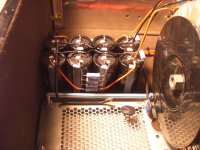
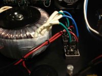
I'm beginning a F5 build. So far I've almost finished the enclosure and started getting the power supply portion built. I tried to P2P the power supply using the First Watt schematic. I thought I was finished, so, I hooked it up to my dim bulb tester (100W light bulb). The bulb is full bright (everything in the power supply connected) and i saw a little smoke come from one of the connections on one of the caps. Does the photos look correct? The transformer is an Antek AN6218 (18v secondaries). With the DC sides of the rectifier bridges disconnected, I'm measuring about 17.7v across the DC side of the rectifiers (shouldn't it be close to 25volts coming out? - also the bulb tester doesn't light up). Also, instead of the .0033 line cap, I have a .0082 in it's place (from an old computer power supply - is this value OK?).
Attachments
I'm measuring about 17.7v across the DC side of the rectifiers (shouldn't it be close to 25volts coming out?
Without caps you won't get DC after the rectifiers, but a rectified sine wave. If you have a true rms multimeter you measure the rms-voltage, so the sqrt(2) reduced value of the peak voltage:
17.7*sqrt(2)=25 V -> ok!
From the photos I cannot see an obvious error, but there is definitely one somewhere.
i saw a little smoke come from one of the connections on one of the caps.
Sound like a good place to start your investigation
")
Hannes
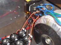
Why do you have the groundstar on the second set of caps?
The first set of caps has a very high current and voltage ripple compared to the ones after the resistor. By the looks of it, those are panasonic caps, I have some of the 10000uf ones, and they are about 0.36 ohms each and have a ripple capacity of about 4A on a good day. even paralleled they might not be up to the task at hand.
Download Duncan's PSUD and simulate what is going on. It is pretty easy.
Of coarse it could just have been some solder flux smokeing off.
Last edited:
On your voltage measurement..... keep in mind you are not measuring pure DC when you measure the output of your PSU rectifiers without the caps connected. Without the filtering of the caps, you are seeing full wave rectified DC, that will be about 70% of your final PSU output voltage. In other words, if you are seeing about 15 volts now, after filtering (and without a significant load, you'll be seeing 141% of your present measurement. That will give you about 25 volts--right where you should be.
Also keep in mind that without a load on your PSU transformer secondary, the transformer PRIMARY will also not see much of a load. Therefore, your transformer will not cause a large voltage drop in the mains voltage--and you'll be applying almost all your mains voltage to the light bulb...therefore, the bulb will be bright. Until you load down your PSU outputs (i.e., with the capacitors, bleeder resistors and amp modules attached [and drawing some bias], yourlight bulb tester will appear to be pretty bright.
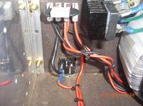
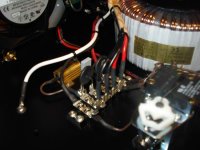
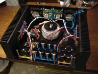
You might want to check the gauge of your wiring between your full-wave bridge rectifiers and caps, and within the cap banks. Same goes, for when you wire between the PSU and the amp modules. I think your wiring is pretty thin. I used, if I recall, about 14 gauge wire...... so pics attached for your info.
I have not done a wire-by-wire tracing of your pics. You might want to triple check, and press on from there.
Also keep in mind that without a load on your PSU transformer secondary, the transformer PRIMARY will also not see much of a load. Therefore, your transformer will not cause a large voltage drop in the mains voltage--and you'll be applying almost all your mains voltage to the light bulb...therefore, the bulb will be bright. Until you load down your PSU outputs (i.e., with the capacitors, bleeder resistors and amp modules attached [and drawing some bias], yourlight bulb tester will appear to be pretty bright.
You might want to check the gauge of your wiring between your full-wave bridge rectifiers and caps, and within the cap banks. Same goes, for when you wire between the PSU and the amp modules. I think your wiring is pretty thin. I used, if I recall, about 14 gauge wire...... so pics attached for your info.
I have not done a wire-by-wire tracing of your pics. You might want to triple check, and press on from there.
Attachments
I consider 100W for the bulb tester too big for good protection.
If the wiring and assembly has already passed the 40W bulb test then you can start increasing the bias using a 60W bulb and go a stage further with a 100W bulb. After that you have to work direct on line, although 10r low power resistors between the cap bank and the new build do help reduce damage when you go askew. Full bias will require 1r0 resistors and maybe even two 1r0 in parallel on an F5.
If the wiring and assembly has already passed the 40W bulb test then you can start increasing the bias using a 60W bulb and go a stage further with a 100W bulb. After that you have to work direct on line, although 10r low power resistors between the cap bank and the new build do help reduce damage when you go askew. Full bias will require 1r0 resistors and maybe even two 1r0 in parallel on an F5.
Last edited:
I contend that smaller PSU wire gauges allow the amplifier to perform better.
Is it because of the added 'r' (to turn a CRC into a rCRC), or is there another reason?
yup ;
but only if one is looking at world solely through PSUD
in my book PSU with lowest internal impedance is best ;
better to put some greenies in better caps , or more caps - than trying to cure with wimpy wires and/or resistors in-line
at least when we are speaking about 1-off building , not commercial one (where one must count on myriad other issues)
Build the PSU with as good as you require internal impedance.
But eventually you have to connect that PSU to the mains and to the amplifier.
Those inherent impedances in the connections cannot be reduced to zero. Never.
So make the best of what we have.
a.) reduce resistance = big cables
b.) reduce inductance = close spaced cables.
c.) increase capacitance = close spaced cables.
I prefer the latter two, having found that big cables did not seem to solve any of my problems, in the way I evaluated the system.
I do have to admit to being a slow learner.
The gap from first adoption of big cables to the fairly recent "discovery" of close spaced wins, is almost 4 decades.
Last edited:
Build the PSU with as good as you require internal impedance.
But eventually you have to connect that PSU to the mains and to the amplifier.
Those inherent impedances in the connections cannot be reduced to zero. Never.
So make the best of what we have.
a.) reduce resistance = big cables
b.) reduce inductance = close spaced cables.
c.) increase capacitance = close spaced cables.
I prefer the latter two, having found that big cables did not seem to solve any of my problems, in the way I evaluated the system.
I do have to admit to being a slow learner.
The gap from first adoption of big cables to the fairly recent "discovery" of close spaced wins, is almost 4 decades.
Hi Andrew,
Appreciate if you could elaborate more on the close spaced cables.
Does it mean shorter wire?
A new slower learner here
I am now a firm believer in twisted pairs.
For AC mains, AC after transformer, DC to smoothing, DC to amp, AC input to amp, flow and return for all controls, AC to the speaker, pulsed DC between PSU and amplifier, etc.
Twisted pairs (or twisted triplets) ensure small aerial area and also go to attenuating the field effects local to the cable. Star Quad seems to be The Best. But is only applicable to a pair of flow and return.
For every Flow there must be a Return. One has to identify the Return and pair it with the Flow for as long as the Flow route exists.
"close spaced cables" excludes any cable pair that has a gap or loop in it.
OK, here's an update on my problem. I took a while off and took care of some other unfinished projects and drank more than a few beers while i pondered. I thought about my problem, and why i wasn't getting proper dc voltage after the cap banks. I thought about the bleeder resistors i have at the input of the caps. I was thinking of power taking the path of least resistance ( i assume this is what's happening). So...i chopped off a lead of each resistor to take it out of the mix. BOOM...I'm sitting around 25 volts now. The dim bulb tester lights up bright and immediately dims (I also took the advice and lowered the bulb wattage). I'll upgrade the wiring next (Dreading the thought of having to dig thru my misc. box of gadgetry). Thanks for the insight and suggestions.
- Status
- This old topic is closed. If you want to reopen this topic, contact a moderator using the "Report Post" button.
- Home
- Amplifiers
- Pass Labs
- Biginning F5 Build - Help with Power Supply