Hi,
I seem to have turned into a collector of old Threshold preamps. Over the last couple of years I bought both an SL10 and then an FET 10/hl preamp and with some minor restoration found them both to be excellent.
I recently came across an FET 10e and FEt 10pe (line and phono) and picked them up and I'm in the process of restoring them. I am going through the usual routine of replacing all the power supply electrolytics, changing the ps diodes to soft recovery types and adding snubbers.
One question I had is about the proper bias for the gain stage output transistors. Both line and phone stages use a universal gain stage which was shared by Zen Mod in an earlier thread http://www.diyaudio.com/forums/pass-labs/167856-new-me-threshold-fet-10-hl-what-refurbish-4.html#post2228075
In the line stage, the bias for the different modules is between 12-15ma. In the phone stage, the bias seems to be a bit lower, being between 8-10ma.
It's probably not too critical but I figure I should at least balance the left and right channels so they're running at the same operating point. Anyone have a suggestion for what that should be?
Besides replacing the electrolytics, I found that the 4.7uf tantalum caps in the servo loop needed some attention. A few of them seem to have gotten a bit leaky causing some but not all of the servos to not quite zero things out. Replacing them with some new 10uf caps worked nicely in the line stage. I also did this in the phono stage. But due to the high DC gain of your typical RIAA stage, you don't get stable DC even with the servo. There is a slow DC drift which I've seen in other phono stages and which has also been described by Syn08 in his HPS 5.1 thread. Can anyone confirm that this is normal for this design?
Thanks,
---Gary
Attachments
bias : you can't do much except changing semis with matched ones ; only that will give same bias in diff channels
servo : have you C8 implemented ?
ZM,
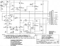
The gain module for the phono stage uses C3, C4, and C8. The line stage does not use them. I did replace C8 on the phono modules. The photo below is taken from a.wayne's pictures of his FET 9e but it uses the same gain modules as the 10pe. C8 is the electrolytic in the bottom left corner, while C3 and C4 are the mica caps along the bottom edge of the board below the transistors with heat sinks.
Regarding the question of whether or not some drift of the DC level of the phono modules is "normal", I'm thinking that it must be since Threshold includes a 10uf output cap even though the modules are servo'd.
One other thing to note is that the schematic differs from the board in one respect. The schematic in the 1st post doesn't show any adjustments. But there is a square blue ten turn pot on the board just above the servo op amp. At first I thought that this pot might allow control of the bias current. Tracing out the circuit, it turns out this is in series with R10 - the output resistor from the servo op amp. My guess is that this resistor is set so that the op amp is operating roughly in the middle of its voltage range.
As I stare at the circuit, I realize that I don't fully understand how the servo works. I'm used to seeing servos fed into the "-" input. But this is being fed into the current sources for the input stage. Nominally, the bases of transistors Q3 and Q4 are fixed by the turn on voltage of D3 / D4. But changing the op amp output will cause more or less current to flow through the diodes and slightly change the voltage of D3 / D4. Which in turn will increase the input current and the current of the next stage. I don't see how the loop closes. Can someone explain how this helps zero the output?
Thanks,
---Gary
Attachments
Last edited:
ZM,it will alter base currents of both Q3 and Q4 , thus altering current through them
rest is logical
Maybe I need a 2nd cup of coffee. I got the first part with the base currents of Q3 and Q4 being altered. It's the "rest is logical" that I'm missing
 . I'll stare at it some more and see if it makes sense later.
---Gary
...One other thing to note is that the schematic differs from the board in one respect. The schematic in the 1st post doesn't show any adjustments. But there is a square blue ten turn pot on the board just above the servo op amp. At first I thought that this pot might allow control of the bias current. Tracing out the circuit, it turns out this is in series with R10 - the output resistor from the servo op amp. My guess is that this resistor is set so that the op amp is operating roughly in the middle of its voltage range...---Gary
Gary,
If you trace the blue trim pot its outer pins 1 & 3 might be connected to pins 1 and 5 of the servo opamp (do a search for LF351N datasheet) and is used for its input offset null adjustment. Pin 2 wiper of the pot would be to -Vcc.
Gary,
If you trace the blue trim pot its outer pins 1 & 3 might be connected to pins 1 and 5 of the servo opamp (do a search for LF351N datasheet) and is used for its input offset null adjustment. Pin 2 wiper of the pot would be to -Vcc.
No - that's the 1st thing I checked and it is definitely not wired up that way. As I said in my previous post, it's wired up to the output of the opamp (pin 6) and is in series with resistor R10.
---Gary
wandering servos
I'm happy to report that after keeping the phono stage powered up for a couple of days, the servos in the phono stage have settled down. I guess that the new electrolytic caps in the servo needed some time to settle down. Now the servo is perfectly quiet and doesn't jump around the way it did when I first replaced the caps. I guess there is something to this burn in phenomena . . .
---Gary
ZM,
The gain module for the phono stage uses C3, C4, and C8. The line stage does not use them. I did replace C8 on the phono modules. The photo below is taken from a.wayne's pictures of his FET 9e but it uses the same gain modules as the 10pe. C8 is the electrolytic in the bottom left corner, while C3 and C4 are the mica caps along the bottom edge of the board below the transistors with heat sinks.
Regarding the question of whether or not some drift of the DC level of the phono modules is "normal", I'm thinking that it must be since Threshold includes a 10uf output cap even though the modules are servo'd.
One other thing to note is that the schematic differs from the board in one respect. The schematic in the 1st post doesn't show any adjustments. But there is a square blue ten turn pot on the board just above the servo op amp. At first I thought that this pot might allow control of the bias current. Tracing out the circuit, it turns out this is in series with R10 - the output resistor from the servo op amp. My guess is that this resistor is set so that the op amp is operating roughly in the middle of its voltage range.
As I stare at the circuit, I realize that I don't fully understand how the servo works. I'm used to seeing servos fed into the "-" input. But this is being fed into the current sources for the input stage. Nominally, the bases of transistors Q3 and Q4 are fixed by the turn on voltage of D3 / D4. But changing the op amp output will cause more or less current to flow through the diodes and slightly change the voltage of D3 / D4. Which in turn will increase the input current and the current of the next stage. I don't see how the loop closes. Can someone explain how this helps zero the output?
Thanks,
---Gary
It looks exactly like a Fet9 phono stage ...
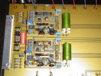
That's because it's a picture of your FET9 phono stage that I took from another thread. I mentioned it in the text that you quoted. Here are some snap shots of the FET10pe. It uses 2 gain modules per channel and of course is a stand alone phono stage, unlike the FET9, which uses 1 gain module per channel and integrated phono and line stage in one chassis.It looks exactly like a Fet9 phono stage ...
---Gary


You might think about upgrading the external power supply.
John,
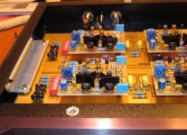
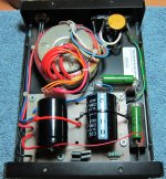
It's definitely on my list of next steps now that I've replaced the old electrolytic and tantalum caps. I already rebuilt the power supply with slightly larger caps (15k uf --> 22k uf), diodes upgraded to Fairchild soft recovery, snubber added across transformer, and some film bypass caps added. Before and after pictures below. I've also got a larger transformer LC supply that I'll patch in for comparison. If that sounds better, which I expect, then I'll build another set of dedicated supplies.
---Gary
Attachments

That's because it's a picture of your FET9 phono stage that I took from another thread. I mentioned it in the text that you quoted. Here are some snap shots of the FET10pe. It uses 2 gain modules per channel and of course is a stand alone phono stage, unlike the FET9, which uses 1 gain module per channel and integrated phono and line stage in one chassis.
---Gary
View attachment 232883 View attachment 232884 View attachment 232885
Well one works betta than 2....
.......err not .. Would the 2 gain stages allow balanced line operation and In beefing up the power supply, would double the transformer rating be sufficient with the bigger caps ..?
Last edited:
Would the 2 gain stages allow balanced line operation and In beefing up the power supply, would double the transformer rating be sufficient with the bigger caps ..?
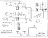
See the schematic in post #2. The 10pe runs two gain modules in parallel for each channel, presumably for lower noise. You can't use them for balanced operation.
Regarding beefing up the power supply, I've built a supply with a 160va transformer that I'm going to try out. Others have reported benefits from going even bigger - say 250va or 300va.
---Gary
Others have reported benefits from going even bigger - say 250va or 300va.
---Gary
OK - I've finished with my power supply experiments and as usual, John Curl is right. This preamp really benefits from a hefty power supply.
First I compared the restored PS (see post #15) to a 160VA LC power supply that I had lying around. There was no comparison - the LC supply was much better. Both supplies had 22,000uf capacitance and roughly the same output voltage. But the transformer in the LC was ~ 2x the VA rating of the stock supply.
With that promising results, I set out to build a really beefy power supply. I got some 18v/18v 300VA toroid transformers from Antek and tried various permutations. First I tried an RC-LC supply, which didn't sound particularly good.
The values I used were:
R = 5ohms
C1 = 4700uf
L = 0.32H / 10 ohms
C2 = 22,000uf
I should have gotten a higher voltage toroid to compensate for the IR drops in the R and L. This supply only had 1v margin over the 18v output of the preamp regulators - not enough. Shorting out the R to make this a CLC supply raised the voltage to 22v and sounded much better. It was now competitive with the LC supply. While 22v (4v margin) should be plenty of margin for the preamp regulators, it's still lower than the stock supply which puts out close to +-24v. I decided to short out the inductors and see how that sounds. It would make the ripple worse but the regulators would have more margin. Vout rose to ~ +-23.3v and the sound got much better. The sound really opened up and became more dynamic with a bigger soundstage.
The final supply is the 300VA toroid 18v/18v to separate Fairchild soft recovery bridges (one for plus and one for minus) to 4700uf + 22000uf. I included snubbers on the transformer secondaries to damp out any diode reverse recovery noise. And I bypassed the electrolytics with 10uf, 1uf, and 0.2uf Russian military caps.
I can bring this to next week's Burning Amp festival if anyone is interested in hearing the difference this kind of supply makes compared to the stock supply.
---Gary
Hi Firends,
I have not yet read the Gary B. feedback on this topic, but we have collaborate together : you can read a full description of the upgrade that I have done on my own Fet-10HE preamp on my website, here:
http://www.thresholdlovers.com/articles.php?lng=en&pg=1162
I will comment later when I have read this topic, but for sure, upgrading the Power Supply brings a huge improvement.
Other upgrades, and particularly replacing the original NOBLE potentiometers with attenuators (I have used GOLDPOINT attenuators as described in the article) brings the same huge improvement...
- Home
- Amplifiers
- Pass Labs
- Restoring a Threshold FET 10e - a few questions