A buddy of mine built an F5, and is having problems with getting enough bass out of larger speakers, like watson lab model 10, tannoy dmt215, maggie 1.6. for example, Bjork's "All is full of love" has tons of deep bass that reaches out and blooms into the room with my modified Phase linear 400 and watson lab model 10. With his f5, the bass never leaves the speakers -- no bloom at all. This track is known for it's insanely rich and room filling bass.
He's hotrodded it to a higher bias, and claims 38 wpc.
He's got 37,000 uF Kendial caps in it, and a 400 VA toroid.
Are the caps bass shy, or is it just that the speaker needs more power? Can he achieve his goal of room filling bass by increasing PS capacitance?
Thank you.
He's hotrodded it to a higher bias, and claims 38 wpc.
He's got 37,000 uF Kendial caps in it, and a 400 VA toroid.
Are the caps bass shy, or is it just that the speaker needs more power? Can he achieve his goal of room filling bass by increasing PS capacitance?
Thank you.
He's got 37,000 uF Kendial caps in it
Is that total or per rail?
It may need to settle in, give it 100 hours use before changing anything.
Is that total or per rail?
It may need to settle in, give it 100 hours use before changing anything.
Per rail. It should be settled in by now.
Try a .47ohm resistor in series with each speaker. This will add some bloom to the base as it lowers the damping factor.
Interesting, I'll pass it on.
BTW: What wattage of resistor?
Last edited:
5 Watt should do it.Interesting, I'll pass it on.
BTW: What wattage of resistor?
let him make hot-rodded F5
you'll find that as cascoded or full blast F5
input is cascoded , outputs doubled
I have the Cviler boards for double outputs. With them plus cascoded front end, what is max rail voltage (for good effect, not absolute max) and bias? assuming plenty of sink...
Russellc

There is a distinct difference between completing a project and testing it to spec, before calling it an F5, vs. "A buddy of mine built an F5, and is having problems with getting enough bass out of larger speakers".
Lets add a Q killing series R in the output and blame it all on the F5
Lets add a Q killing series R in the output and blame it all on the F5
No one has mentioned any testing of the amp? Try testing freq response into an 8 ohm resistor. Is it the amp or the load?
I go with this statement.
And also with this:
Lets add a Q killing series R in the output and blame it all on the F5
Any resistor in series with the speaker is crap.
Franz
OK, so what needs testing before you can call it an F5? What do you need to see?
It biases up nicely, there is next to no DC, all the parts are reputable ( I'm guessing that the PS caps are not fake) , it's using the Peter Daniel boards.
What tests? Just frequency response?
The load is extreme. The watson Lab model 10's impedance drops to below 2 ohms in the bass. There are two 36 Oz magnets each side, driving mass loaded woofers -- they have plastic dinner plates glued to the cones. There is probably a lot of back emf to deal with here.
Well, freq response is a good start, sinse the system in question seems to have a frequency related problem. And now, the truth comes out, impeadance dropping to 2 ohms. O.K. That is a difficult situation however, I seem to remember something about not burping into 2 ohms. This does sound a little like a burp?
A response test is normally conducted with a fixed load ie;2, 4, or 8 ohm resistors. Some even get fancy and add in capacitance and inductance to actually model a speaker load. I think to deal with such impeadance variation it's important to have good damping factor. A Damping factor of 80 sounds good until you actually calculate what the spkr Z variation does. Damping Factor drops to 20 with a 2 ohm dip.
You probably want to monitor your supply rails during some of the more strenuos tests with a scope if possible.
You should also look at the full power response down in the low freq area. Check for clipping levels also.
One thing to check I think would be the current limiting circuit, if it has one. Due to component variance and such it could be limiting at lower current than the 10A suggested in the article. As a practical matter in this particular situation, you might consider raising the limiting threshold.
That should get you started
You might want to read http://www.diyaudio.com/forums/pass-labs/182966-f5-low-z-loads.html
O.K. That is a difficult situation however, I seem to remember something about not burping into 2 ohms. This does sound a little like a burp? A response test is normally conducted with a fixed load ie;2, 4, or 8 ohm resistors. Some even get fancy and add in capacitance and inductance to actually model a speaker load. I think to deal with such impeadance variation it's important to have good damping factor. A Damping factor of 80 sounds good until you actually calculate what the spkr Z variation does. Damping Factor drops to 20 with a 2 ohm dip.
You probably want to monitor your supply rails during some of the more strenuos tests with a scope if possible.
You should also look at the full power response down in the low freq area. Check for clipping levels also.
One thing to check I think would be the current limiting circuit, if it has one. Due to component variance and such it could be limiting at lower current than the 10A suggested in the article. As a practical matter in this particular situation, you might consider raising the limiting threshold.
That should get you started
You might want to read http://www.diyaudio.com/forums/pass-labs/182966-f5-low-z-loads.html
Last edited:
Hmmm...
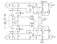
You may have a look at the Watson Labs Model 10 crossover image:
WATSON LABS MODEL 10 SPEAKER
I cannot find any impedance information about this crossover/speaker.
Is the sensitivity true 93dB/W ?
Do you have the schematics of the crossover network, at least the part for the woofer?
Maybe this is a unhappy combination, a F5 driving WL Mod 10?
Franz
The F5 is a 1pr output stage.
It should be great driving a conventional 8ohm speaker.
It can also drive a conventional 4ohms speaker. But I will add the proviso that I think a 1pr output stage will suffer current starvation when presented with typical 4ohms speaker reactances.
Driving a 2ohms to 8ohms speaker from a 1pr output stage seems downright daft.
let him make hot-rodded F5
you'll find that as cascoded or full blast F5
input is cascoded , outputs doubled
Okey dokey sound reasonable but could you give us same numbers.
Yess I know asking for straight answer leave you open to same others criticising and caming up with all wrong reasons (a bit like putting your man vegetables in to an edison lamp holder and stiking a note "do not use" by the switch)
So what about twin mosfet 26 V rails 3.6 A (1.8 A mosfet) and no current limiters.
I Tested the lot with my ancient set up (bit worn by to much uso and such and ear wax ridden) and it did fine by me on a pair of Plonk LSi15 or wasit LS15i. (4 homs 87 dB nominal)
+ plenty of room to play with speaker position and sides (to be or not to be woofer firing up to wall)
hups forgot litle thing 200mU on each raill.
So what is got to be more currants on the bias? more caps for the currants?
or maybe just move the speakers a litle bit?
Maybe just all 3 but IMO (IMO = red togle cover on top off please do not use switch) wel worth the effort as the F5 £ for £ is the best IMO
Yes, my request seemed a little open ended as well, maybe if I narrow a little....The schematic I see shown around here for the cascoded front end indicates up to 45 volts, most of the threads I've looked at have been around 30 or just over. I'm just wondering if 45 volts is given as a max, and there is no advantage to going that high. Just wanted to know if there was a particular sweet spot in terms of rail voltage in this setup. Also wonder if durability of the jfets falls off at higher voltages. Similar for the bias on the dual output F-5. Threads show this as well, just wondering if there is a place where no more advantage is gained, or life span of the Mosfets is compromised?
Russellc
Russellc
- Status
- This old topic is closed. If you want to reopen this topic, contact a moderator using the "Report Post" button.
- Home
- Amplifiers
- Pass Labs
- Adding bass to an F5?