Probably I should add that I was concerned about the dissipation. As far
as I can tell, Sony didn't offer curves showing instantaneous dissipation
beyond about 80-90 watts, and they had a similar chip rated at 65 watts.
Out of concern for reliability, I didn't push it beyond 1/2 that.
If I read your data correctly, you are at about 100 watts dissipation on yours,
and I would certainly expect better numbers from that, but in addition I think
you've found the "sweet spot".
I don't have the output centered. I'm at 17.5 Vds for around 50W dissapation. The rest is across the bulbs, and I have a little negative supply for the bias.
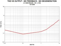
A little further tweakery reduced the 1W THD still further. I think that's about as sweet as I can dial-up. I'm going to build another one and give them a listen.
Thank you, Neslon. I'm encouraged. This sweet spot stuff is pretty fun.
Mike
P.S. Does the low (2X) voltage gain figure seem correct? Also, I believe my samples have the drain connected to the body as the other way around had no gain and worse distortion.
Attachments
Breaking news: the 2SK82 was rated at 95 watts (25 deg C case temp).
Also, my single-ended result had 3 dB of gain.
Good news there!
I might note that I expect 300 light bulbs to come out around 22 ohms. With 2 in parallel, that would be 11 ohms, so something's off.
I'll check all that and try another device to be sure. I have my gates set at -3V.
Thank you. Have fun at the coast!
Mike
Nelson,
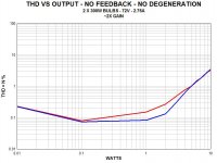
I wired two of my bulbs (GE Crystal Clear 300) in parallel, and with 54V across them they draw 2.8A, for about 20 Ohms.
I also cleaned up my bench prototype and double-checked everything to be sure my results were repeatable. Then I replaced the 2SK82 with another, just for good measure and the results were the same.
I now feel pretty confident that I'm giving you good information with respect to the pinout as well as the THD results. Now I'm off to work up the plywood prototypes.
Thank you,
Mike
Hello, Michael
When using 2SK82 in the common source stage, we might need to care of possible limitations. I do not have a datasheet for K82, but looking at this japaneese site
ƒvƒ‰ƒ“‚ ‚ꂱ‚ê
I have realised that they struggle against the huge capacitances of K82, something (as a guess from the google-translated text) near Ciss + Crss = 4000pF, and they use four-stage schematics for driving them properly.
Apart from the THD and enjoyment from simple schematics, we should assess what can be expected soundwise, IMHO.
I read that the 2SK82 has 2 dies and they have to match or one will die!
Did you get them from the Singapore seller on Ebay?
My information is that it is a single 4mm die.
Looks like Mike cleaned out Acronman.
I have realised that they struggle against the huge capacitances of K82, something (as a guess from the google-translated text) near Ciss + Crss = 4000pF, and they use four-stage schematics for driving them properly.
Not so bad. You'll notice in the schematics that they are using 680 ohm
gate stoppers on them.
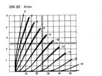
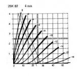
Working with Nelson's K82 graph, I have drawn two loadlines for illustration. (see attach.)
You need to use a 'millimeter ruler' and position it in such a way, that the spacing in mm on the ruler will be equal between the adjacent Vgs lines
from zero Vgs to the max Vgs.
First, the top line.
We cannot go below -14V because of the distortion, so the the Vgs bias is 14/2=7 V.
At the loadline -7Vgs will produce 2.4A Id and 18V Vds. 2.4*18=44W dissipation at idle.
The drain will swing between 7.5V and 27V.
27-18=9V
18-7.5=10.5V,
so one half will have higher amplitude = even harmonics, mainly second.
Load resistance calculated from coordinates crossing.
28V-7V/5A=21/5=4.2 Ohm
So, the optimal load will be 4 Ohm speaker. To make load look like 4 Ohm
with the 8 Ohm speaker, we will have to parallel it with 8 Ohm resistor, which will seriously compromise the efficiency.
Another way is to use a 8 Ohm:4 Ohm (1:1.414) transformer.
Taking 10V output amplitude, output power will be 10²/2*4=12W.
Obviously, we can reposition the LL to cross the -14Vgs at 28Vds, or more. In any case, having some of the second harm. will help to balance the spectrum against the unavoidable third.
Voltage gain (deltaVd / deltaVgs) with this loadline will be ~1.2-1.5 (3dB). The input signal will have ~7V amplitude.
With source follower configuration the gain will be ~0.6, or so.
The lower LL is another try. Here we have to limit the Vgs swing to only 13V, because -14V is already distorted too much.
Vgs=13/2=6.5V.
At this Vgs the Id=2.2A, Vd=15V. Power diss. at idle 2.2*15=33W.
From LL crossings 23V-5V/5.1A=18/5.1=3.5 Ohm.
Now, we can use 4 Ohm speaker with the calculated resistor (lightbulbs) in parallel to produce the desired load value for the V-JFET. Obviously, same limitations here for an 8 Ohm speaker.
Another issue to keep in mind is the speaker low freq. resonance impedance (much higher, than 4 Ohm).
So, the optimum drain biasing solution will be a low inductance CHOKE with Rdc=4 Ohm, and staying at that AC impedance level at all low end freq., where the speaker impedance is still too high. In other words:
X=2*pi* (~150 Hz)*L=4 Ohm, and
L=4/6.3*150 ~=4 mH
Clearly, all these V-JFETs will be different, and will require individual measurements (curve tracing).
Attachments
Last edited by a moderator:
Looks like Mike cleaned out Acronman
I hope I didn't buy the last four in existence. I've got half an article written.
- Status
- This old topic is closed. If you want to reopen this topic, contact a moderator using the "Report Post" button.
- Home
- Amplifiers
- Pass Labs
- 2SK82 + Lightbulbs = Fun