I have a question about the mininum space that a toroidal transformer can be mounted to the enclosure side wall/heatsinks? I have a project that I want to build, but I am worried about the space between the sides of the enclosure and the toroid. I have a total of 4.5mm to 5mm on either side of the toroid.
Is there any mechanical problems that will be a deal breaker? Insulation between the heatsink and toroid is no problem just curious if it will humm, buzz, etc.
I will try to shoot a pic later,
Thanks for any input
Steve
Is there any mechanical problems that will be a deal breaker? Insulation between the heatsink and toroid is no problem just curious if it will humm, buzz, etc.
I will try to shoot a pic later,
Thanks for any input
Steve
humm, buzz
That's usually due to the design of the toroid and/or due to DC on mains. So far I haven't had any issues with noise due to close mounting to metallic parts (noise due to proximity to the pcb I know however very well).
Hannes
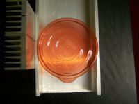
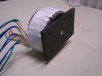
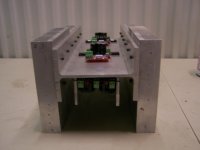
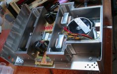
Here is what I am working with. This is a 15.75inch long Aluminum I beam. I want to cut out a notch and mount the toroid on the bottom along with both PSU PCB. I have a Antek 5415 toroid 4x15V 400VA to make a dual mono block Mini Aleph with.
I will then attach my heatsinks to the I beam, and the notch will provide the clearance i need to fit the toroid into the design. I can turn on its side and cut out extra material, however, That would remove material and effect heat transfer from from to back, and the amp PCB would not be shielded from the power supply.
I am hopeful that this will be possible. The bowl lid is the same size of toroid, here you can see how close it really is!
pic attached:
Attachments
and the amp PCB would not be shielded from the power supply.
Alu does not provide any shielding as also iron does not. Count only on mu-metal for significant shielding.
Keep the pcb at least 10cm away from the toroid (certainly more is better), otherwise you've great chances to get nice humm. (depends on wether its only the output stage board or there is some voltage amplification as well going on)
Hannes
Last edited:
go ahead, but don't expect any magnetic attenuation.
Ferrous materials will modify the magnetic fields around the toroid transformer.
buzz due to winding or lamination vibrations are best reduced by vac vac varnish impregnation.
buzz or hum or grumble due to non symmetrical AC mains waveform is best reduced by a DC blocker in the primary circuit. Research this thoroughly. There are very severe risks if done incorrectly.
I am glad to find out that the small mounting area should not cause any problems. I can proceed with building the case now. I have had the amps running for some time now with no humm, buzz, or any other problems. I know that alot of things come into play, and that when I started to case this amp up I might run into something.
Thank you for the information and now its time to drill.
I will update soon.
Steve
Thank you for the information and now its time to drill.
I will update soon.
Steve
In my experience,the most important things to consider are; avoid mounting active circuits or pc boards too close to the transformer to aviod hum from magnetic field leakage as was already mentioned, especially along the mounting bolt axis where the field has the most strength; don't mount the transformer to the chassis so that the mounting bolt creates a shorted turn, bolt and mounting hardware should contact chassis at only one point; and be sure transformer has adequate air exposure for cooling.
Mike
Mike
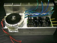
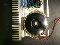
UPDATES
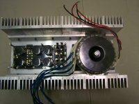
Here are some pics.
All fab work is about done. I will finish the back panel AC input, XLR, Power switch tonight, and then run all the wires also.
Then tear it all down and clean, prep, and finish it up.
This thing is a TANK!
Here are some pics.
All fab work is about done. I will finish the back panel AC input, XLR, Power switch tonight, and then run all the wires also.
Then tear it all down and clean, prep, and finish it up.
This thing is a TANK!
Attachments
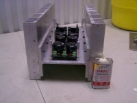
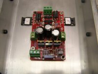
Another "area of interest"--the primary radiating surface of the heatsinks is a considerable distance from the heat sources (semiconductors). This can really reduce the efficiency of the heatsinks in cooling the MOSFETs. Best to very carefully monitor your MOSFET temps as you bias them.
In addition, since the I-beam is bolted to each heatsink in only two places (or so it appears), you have to watch the thermal conductivity at the surface of the I-beam to the surface of the heatsinks--both mating surfaces should be very flat, and more fasteners would help--and some thermal grease might be useful. (Whenever I'm are concerned about thermal mating, I'll use a milling machine on both mating surfaces to get a true flat surface......either that, or lap them in with a valve grinding slurry, and a piece of thick glass as a "truing surface")
In addition, since the I-beam is bolted to each heatsink in only two places (or so it appears), you have to watch the thermal conductivity at the surface of the I-beam to the surface of the heatsinks--both mating surfaces should be very flat, and more fasteners would help--and some thermal grease might be useful. (Whenever I'm are concerned about thermal mating, I'll use a milling machine on both mating surfaces to get a true flat surface......either that, or lap them in with a valve grinding slurry, and a piece of thick glass as a "truing surface")
I absolutely agree Andrew, a few years ago I got some heatsinks that came with a cheap stereo amp kit. After the outputs on one channel blew I discovered the heatsink mounting surfaces weren't flat, resulting in fried transistors. I had them milled flat at a machine shop in the area and the problem was solved. Ironically, the milling service cost nearly as much as the amp kits.
Mike
Mike
CanAm Man got it right
Remind me of my prentice days hand lapping 130Hp Volvo Penta heads
IF I may
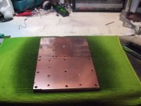
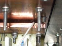
I did hand lapping on my sinks and heath spreaders.
By hand lapping I mean rub one against the other in small circles on the place where they are meant to sit
I started with emery paper on a granite surface to get them flat then spreaders against sinks I had a spare granite tile so no risk of breaking mirrors and such which still vuld work fine.
As you have many small sinks this shuld work well.
Once most of the 600-grain paper scratches where of with fine carbide I started using varnish scratch remover and baking soda or tooth paste work fine as well
You may notice how mirror like one spreader look next to the other
After about 10 hours and having cleaned the lot a few times the heat spreader where sticking to the sinks as if magnetized (Yea I know cooper and aluminium do not get magnetized but that is how it felt like) maybe same professor here would care to explain.
To complete the assembly I used graphite heat sink grease at 10W/mK is about 3 times than the best silicon grease.
Farnell PNO is 1315296
This grease is conductive so no good for the mosfets for which I use Keratherm 86/83.
I must say your build looks really good but if you need to improve on the thermal load
Why not having it anodised
They may even do the lot all bolted togheter
Normally they charge a flat fee no matter what quantity you have and eficency of the sink is much better (I am not going to post numbers that you can find on Wikipedia)
While there you can wikipediaup Graphene there is a bit that mention Scotch tape method it works fine with Mica as well
Remind me of my prentice days hand lapping 130Hp Volvo Penta heads
IF I may
I did hand lapping on my sinks and heath spreaders.
By hand lapping I mean rub one against the other in small circles on the place where they are meant to sit
I started with emery paper on a granite surface to get them flat then spreaders against sinks I had a spare granite tile so no risk of breaking mirrors and such which still vuld work fine.
As you have many small sinks this shuld work well.
Once most of the 600-grain paper scratches where of with fine carbide I started using varnish scratch remover and baking soda or tooth paste work fine as well
You may notice how mirror like one spreader look next to the other
After about 10 hours and having cleaned the lot a few times the heat spreader where sticking to the sinks as if magnetized (Yea I know cooper and aluminium do not get magnetized but that is how it felt like) maybe same professor here would care to explain.
To complete the assembly I used graphite heat sink grease at 10W/mK is about 3 times than the best silicon grease.
Farnell PNO is 1315296
This grease is conductive so no good for the mosfets for which I use Keratherm 86/83.
I must say your build looks really good but if you need to improve on the thermal load
Why not having it anodised
They may even do the lot all bolted togheter
Normally they charge a flat fee no matter what quantity you have and eficency of the sink is much better (I am not going to post numbers that you can find on Wikipedia)
While there you can wikipediaup Graphene there is a bit that mention Scotch tape method it works fine with Mica as well
Attachments
Last edited:
re: Toroid Transformer mounting
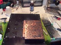
Below shows several plies of 16 gauge steel used to enclose a torroid and chokes. Top covers removed. (Not quite done with this, yet.)
ThorstenL: I learned things I NEVER wanted to about how magnetic fields behave . . .
Below shows several plies of 16 gauge steel used to enclose a torroid and chokes. Top covers removed. (Not quite done with this, yet.)
Attachments
Last edited:
Tanks sippy
Coupling and heath transfer gotta be good then.
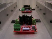
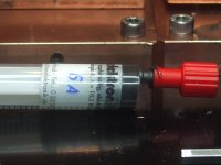
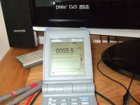
Temperature mesured on tab of a FQP19N20 (TO220) 55.5 sinks at 42 C
I have at present 26 V rails and bias set at 2.8 A
Thermal load on sinks about 145 W for the 4 mosfets (2 on each rail)
Apart from meter capable all you need is a PT100 probe the 1 I use is 1.2 X 2.4 mm, perfect for tight spaces, conected to grey cable on picture 1
Coupling and heath transfer gotta be good then.
Temperature mesured on tab of a FQP19N20 (TO220) 55.5 sinks at 42 C
I have at present 26 V rails and bias set at 2.8 A
Thermal load on sinks about 145 W for the 4 mosfets (2 on each rail)
Apart from meter capable all you need is a PT100 probe the 1 I use is 1.2 X 2.4 mm, perfect for tight spaces, conected to grey cable on picture 1
Attachments
Last edited:
- Status
- This old topic is closed. If you want to reopen this topic, contact a moderator using the "Report Post" button.
- Home
- Amplifiers
- Pass Labs
- Toroid Transformer mounting question