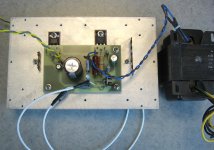
Attached is a photo of the first proto of an SE amplifier( the "SiC Puppy") using the Semisouth 085 silicon carbide JFET in the output stage. The front end uses the Supertex DN2540N5 depletion mode mosfet. I choose the Semisouth part over the IXYS depletion mode parts due to the extra headroom afforded by the 1200V rating, allowing me to choose B+ voltages with a bit more freedom. The circuit (to follow) is set up just as if the two parts were pentodes, with partial feedback from the output drain to the input drain, plus a limited amount of global feedback (disconnected at firtst. I used the One Electron UBT-1 1.6k transformer because I had a pair on hand. The output stage bias is set for the maximum primary current rating of the UBT-1 (150 ma). Next is a power-up with a DC supply to chcek stability of the output bias.
The heat sink is one of Papa Zen's giveaways from the very first Burning Amp in October 2007. I'm thinking of running the amp in a dual mono configuration using a pair of ~150VA step-up/isolation tansformers, which when configured for 230V output and rectified will give me ~320VDC B+. There is an on-board capacitance multiplier for ripple reduction, feeding a 270uF bulk capacitor.
More to come - this is just the first heads-up.
Attachments
I'm thinking of running the amp in a dual mono configuration using a pair of ~150VA step-up/isolation tansformers, which when configured for 230V output and rectified will give me ~320VDC B+.
320VDC fer solid state??? Whhhhhhhhaaaaaat!!!!

C2 - You can go ahead and run that 1200V part at 12V if it makes you feel better....
This was an exercise to sub some new generation semiconductors into a basic tube circuit. Others are trying the Semisouth part with a special wound transformer (300 ohms, I think) that will allow operation at lower voltage, higher current. I happened to have a pair of One Electron UBT-1s (1.6k, 150 mA) on hand. If the circuit sounds decent, I also have a pair of the monster Triode Electronics 1250 ohm, 30W SE transformers on hand. The Semisouth parts should exploit their full capability. They also have an ultralinear tap, so I could try some "E-linear" type circuits using one of the higher voltage IXYS depletion mode parts for an input device.
This was an exercise to sub some new generation semiconductors into a basic tube circuit. Others are trying the Semisouth part with a special wound transformer (300 ohms, I think) that will allow operation at lower voltage, higher current. I happened to have a pair of One Electron UBT-1s (1.6k, 150 mA) on hand. If the circuit sounds decent, I also have a pair of the monster Triode Electronics 1250 ohm, 30W SE transformers on hand. The Semisouth parts should exploit their full capability. They also have an ultralinear tap, so I could try some "E-linear" type circuits using one of the higher voltage IXYS depletion mode parts for an input device.
Last edited:
C2 - You can go ahead and run that 1200V part at 12V if it makes you feel better....
eh - I've played with tube and HV for a looooooog time - so 320VDC isn't something I would be afraid of. Ya just don't see that sortta voltage around SS devices very often. I haven't paid much attention to the uses of that particular device - you got my attention.
One thing I've found out from this exercise so far is that it pays to read the data sheets closely. The Semisouth 085 part has a rather large gate leakage (~100 uA!!!!!), so you don't have a lot of freedom regarding gate pull-down resistance and interstage coupling caps. This I discovered after my prototype ran away at high input voltage. To make a long story short, you need to have a gate pulldown of 10k or less if you want to play with linear operation at high drain voltage. I had 330k instead, so the runaway was understandable. This means you need a hefty interstage coupling cap. Fortunately, I have some suitable 3uF, 450V polypropylene caps hanging around at home. These and the proper pulldowns will go into my prototype tomorrow. With all the proper stuff in place, the source should be running 7-8V above the gate at 150mA drain current, 300V drain voltage. I may also use aluminum oxide insulators for better thermal coupling and dielectric peace of mind, but I'll have to order those.
You will want to characterize individual parts at the voltages, currents and
temperature in order to know the actual Gate leakage. There is variation,
so you can select for low leakage - I have some at 1 uA and some at over
200 uA. So far this only appears to be an issue with regards to the output
impedance of the bias circuit.
temperature in order to know the actual Gate leakage. There is variation,
so you can select for low leakage - I have some at 1 uA and some at over
200 uA. So far this only appears to be an issue with regards to the output
impedance of the bias circuit.
Nice (but not so comforting to know) that the leakage varies such that you can select for a low leakage part. Sounds like SemiSouth is still in the "Wild West" stage of development. I'll just use the 10k and 3uF for right now and sleep soundly - I most likely have gain to burn in both stages of my amp, so the first stage loading may not matter that much. I could fix all of this by adding a follower stage. I may try this in subsequent revs of the circuit so I can mix low voltage and high voltage technology. I do it all the time with tubes so that I can run AB2 or A2 without too much pain, so it's not a real stretch to use similar measures in this project.
The inconsistency (and indeed, the high leakage to begin with - this is far worse than Si parts with much lower breakdown voltages) will be an issue (does it mask or harbinger other issues? Does the company really have their process under control?) to those who might want to use it in a consistent manner in its intended switching application in mass production, especially as their customers expect low PPM failure rate (and really get worked up even about that) under all sorts of conditions, all for a pittance. I'll be asking some questions back-channel, though that really doesn't have that much to do with matters here.
I'll go ahead and use a low impedance driver circuit of some sort for this project, but I don't really like it all that much - it takes a fair amount of the shine off the part, especially given the high asking price. It'll be interesting to see if similar GaN parts work any better.
I'll go ahead and use a low impedance driver circuit of some sort for this project, but I don't really like it all that much - it takes a fair amount of the shine off the part, especially given the high asking price. It'll be interesting to see if similar GaN parts work any better.
or SiC's, as Class D drivers for Electrostatics?
A second thought: possible to use the SiC's in their switching mode, as pulse-width modulated (Class D) drivers for ESLs? Depending on the PWM switching frequency, feasible for the ESL network to filter out?
Just thinking out loud.....
Potentially some interesting opportunities for direct drive electrostatics...... Anyone care to chime in?
it takes a fair amount of the shine off the part, especially given the high asking price. It'll be interesting to see if similar GaN parts work any better.
You can always use a Mosfet, where the Gate leakage is virtually zero.
Unfortunately I haven't encountered a Mosfet that sounds as good as these
parts.
Still working on thermal and bias stability issues. It looks like the part will need the very best insulator pad in order to dissipate the heat without undue temperature rise. I'm going to order some aluminum oxide pads from Mouser. Even though the part is SiC, I want to keep the die temp at 100C or below. I also don't know anything about the tempco of the gate leakage, though I would assume that it would rise with die temp. At present, I'm getting about 0.15V gate voltage with a 10k gate pulldown, meaning I'm getting about 15uA of gate leakage. The part I have in the board right now needs about 12V of reverse bias for 150mA - I may change it for one with lower reverse bias requirement, as this makes the source resistor rather toasty.
To make it clear, I'm continuing with the Semisouth parts on this design, as they have the dissipation capability and voltage rating to run comfortably at vacuum tube voltage levels. The Ixys 500V parts would be a little marginal for the application unless I ran higher drain currents and lower B+, which is not compatible with the transformers I'm using. I have other plans for the Ixys depletion mode parts I have on hand. I just characterized a lot of 10 pieces for Vgs at 1A drain current in order to get some matched pairs. A possible project with these is a Susan Parker "Zeus" amplifier. I may also try something similar to what Nelson has done commercially with the Semisouth parts, but using the Ixys parts instead. These projects will get separate threads when I actually start something.
- Home
- Amplifiers
- Pass Labs
- "SiC Puppy SE Amp Using Semisouth 085 JFET