it is the One Electron UBT-1
Q: Why do electrons all have exactly the same charge?
A: Because there is only one.


Buzzforb - using any more voltage on the B+ is a waste, as I'm right at the comfortable (actually, not very comfortable) limit for dissipation in a single TO-247 device, about 45W. I don't want to reduce the bias current to accomodate higher input voltage. If I did anything, I would reduce B+, increase bias current, and use a transformer with lower primary impedance (hotter turns ratio - more output voltage for a given input voltage). I have a Triode Electronics transformer that might just fill the bill, but I'm not going that route for quite a while.
This design was an exercise in adapting a standard tube amp topology for semiconductors, and I explicitely designed the circuit to utilize output transformers I already had on hand, hence the 300V B+ and 150 ma bias current, which is right near the maximum current rating for the One Electron UBT-1 transformer, also right at the limit for dissipation in a single TO-247 package. I opted to go for comparatively low voltage and relatively high bias current, as I judged that to be closer to the "sweet spot" of the Semisouth part. You could use higher voltage, lower bias current, and a higher impedance/turns ratio transformer, but that may not be optimum usage. I won't be doing a whole lot of messing around with those kinds of combinations, as it is both an expensive and time consuming exercise. An alternate approach using lower voltage, higher current, and a special output transformer is the "Nemesis", detailed elsewhere in this forum.
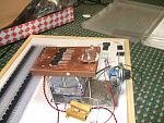
The project at present has proceeded far enough so that I have gotten two prototype channels to run with a bench supply. Sonic results from that setup were encouraging enough so that I want to box the amp wth a real power supply and a fan for extended listening tests with better audio components than were available in the lab. This will also allow me to do some measurements in a less noisy and life-threatening environment. This next step will take a while, as I haven't had a chance to search for an appropriate case, or figure out an alternate packaging aproach that won't take too much time and won't end up looking like Sh**. This design is also being time-division multiplexed with about six others, a full time job, a college radio DJ gig, and basic life maintainance functions. I will describe progress as it happens. If anyone else wants to forge ahead on a similar front and scoop me, be my guest.
This design was an exercise in adapting a standard tube amp topology for semiconductors, and I explicitely designed the circuit to utilize output transformers I already had on hand, hence the 300V B+ and 150 ma bias current, which is right near the maximum current rating for the One Electron UBT-1 transformer, also right at the limit for dissipation in a single TO-247 package. I opted to go for comparatively low voltage and relatively high bias current, as I judged that to be closer to the "sweet spot" of the Semisouth part. You could use higher voltage, lower bias current, and a higher impedance/turns ratio transformer, but that may not be optimum usage. I won't be doing a whole lot of messing around with those kinds of combinations, as it is both an expensive and time consuming exercise. An alternate approach using lower voltage, higher current, and a special output transformer is the "Nemesis", detailed elsewhere in this forum.
The project at present has proceeded far enough so that I have gotten two prototype channels to run with a bench supply. Sonic results from that setup were encouraging enough so that I want to box the amp wth a real power supply and a fan for extended listening tests with better audio components than were available in the lab. This will also allow me to do some measurements in a less noisy and life-threatening environment. This next step will take a while, as I haven't had a chance to search for an appropriate case, or figure out an alternate packaging aproach that won't take too much time and won't end up looking like Sh**. This design is also being time-division multiplexed with about six others, a full time job, a college radio DJ gig, and basic life maintainance functions. I will describe progress as it happens. If anyone else wants to forge ahead on a similar front and scoop me, be my guest.
I appreciate the answer. I wasn't inquiring about the possibilty of more voltage, just wondering how it would compare sonically to the same transistor with 80V supply and 2A of bias. AS you said, these devices allow us to run them as if they were tubes and it would be interesting if its the operating points that determine the "tubey" sound. I know this is a long shot and maybe even stupid, but interesting all the same.
As I pointed out, there are people who are running the Semisouth devices with a lower B+ and much higher bias current (with a suitable transformer), though not necessarily the same topology. I wasnt aiming for any sound in particular, but wanted to see how the devices would perform given a set of design constraints. I liked the sound enough to proceed.
People who want to flap their ears at the end procuct can do so at the next Burning Amp.
People who want to flap their ears at the end procuct can do so at the next Burning Amp.
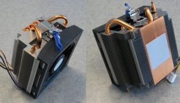
On that front, I just scored home heat pipe-type coolers on the big Pay that may be up to the task of cooling both channels. The fan noise remains to be ascertained, but maybe I can afford to starve the fan voltage to reduce the noise level. The whole assembly will be inside a case, which should also help.
The operating points, and thus the load-line, largely determine the
"tube-osity".
Nice term, Nelson, I would also add, for widening a picture, that "tube-osity" will depend also on Ciss and Crss, their magnitude and variation with Vds. When we will approach to Ciss=10pF and Crss=1pF with "stone" parts, tubes for sure will be trashed.
My heat pipe CPU coolers arrived. They are supposedly good for 125W or so. Mounting them to the heat spreader plate to interface with the amps will be a bit of challenge, as I probably won't be able to drill into the copper heat coupling plate on the cooler for mounting screws without hitting the heat pipes. Creative use of the included CPU mounting clips may be the way to go. Who says you can't do a compact Class A amp?
Attachments
Last edited:
Wrenchone
Coolers are good for that 125W and more had one on old FX55 now retired and it was on cooling duty for my mosfets till yours truly inverted + - vires
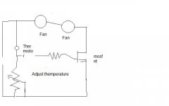
If you got spare mosfet spare 4.7 K thermistor and spare pot themperature controller is easy peasy sorry for chiken scratch.
Thermistor on heat sink resistance drop as heat goes up which make mosfet conduct more fan goes faster
Set pot for fans to tick over just when heat is getting up.
Fans at 75 % of rated voltagge are dead quiet.
You would have to clamp cooler to same plate easy once you rip off the clamping braket and use goop of your choice
Coolers are good for that 125W and more had one on old FX55 now retired and it was on cooling duty for my mosfets till yours truly inverted + - vires
If you got spare mosfet spare 4.7 K thermistor and spare pot themperature controller is easy peasy sorry for chiken scratch.
Thermistor on heat sink resistance drop as heat goes up which make mosfet conduct more fan goes faster
Set pot for fans to tick over just when heat is getting up.
Fans at 75 % of rated voltagge are dead quiet.
You would have to clamp cooler to same plate easy once you rip off the clamping braket and use goop of your choice
Attachments
Nice term, Nelson, I would also add, for widening a picture, that "tube-osity" will depend also on Ciss and Crss, their magnitude and variation with Vds. When we will approach to Ciss=10pF and Crss=1pF with "stone" parts, tubes for sure will be trashed.
IIRC that term was coined by the Late Harvey "Dr Gizmo" Rosenberg. I think NP may have had his inside joke.
For my current project I'm gonna use additional cpu coolers too (CoolerMaster TX2). They're cheap when you buy them used, because the first generation is a faulty design concerning the plastic mounting clips for the motherboard. I'm planning to use the chunks without fans. A no-noise solution with an inside duct (is this the right word for it?) providing a chimney-effect is my favorite.
Last edited:
I just powered up one of the coolers on the bench a short while ago - the fan draw at 12V is relatively modest (120 ma), and the noise level is surprisingly low. I have some other coolers of more modest capacity that are real whiners at full tilt (like some list members). Next problem is how to interface the CPU clips to my heat spreaders - noise will be a non-issue.
- Home
- Amplifiers
- Pass Labs
- "SiC Puppy SE Amp Using Semisouth 085 JFET