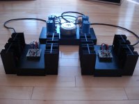
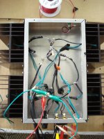
20 years ago I purchased a40 circuit boards and partial parts from Old Colony. I got as far as stuffing the boards, then life happened. Just recently, I was afforded the opportunity to finish the amp – see a40 pic attached sans perforated chassis covers.
Sounds great, but there is oscillation in the amp and comes across as a high frequency buzz. See attached pics.
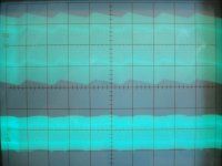
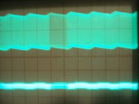
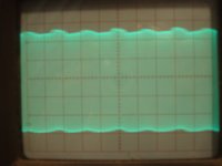
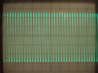
Scope1 jpeg. The top trace is the +32v rail. Scope settings: 2v per div vertical and 5ms per div horizontal. The bottom trace is the output of the amp into an 8 ohm speaker load at 1v per div.
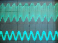
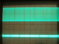
Scope2.jpg, same settings as above except I cranked the time per div out to .5us per div.
What I have done so far:
Got feedback from Mr. Pass (thanks so much!) pointing out I could use more capacitance (hence replacing the 20 year old caps) and noted the RF noise. Replacing the caps greatly reduced the hum.
Found Erics great a40 site (thanks Eric!) and rewired the amp plus moved the caps/bridge rectifiers around to minimize noise and same for the wires going to the bias on Q7 and Q8.
Tried testing the FET 2N5248 as per Eric’s site, but did not get reliable readings with the ohm meter. So can’t be 100% sure these are installed right.
What should I do?
Somewhere I read that the Old Colony boards needed a trace modification, but I can’t find what it is exactly.
Looks like a snubber RC across the bridge rectifiers would really help (as per Erics site), but I don’t think I have the gear or know how to correctly measure and calculate the RC values. Any suggestions for the RC values?
Looks like putting a 4.7uf film caps like http://www.partsconnexion.com/capacitor_film_axon.html across the electrolytic caps would help?
Does this make sense? Any other suggestions?
Best regards,
Mitch
Sounds great, but there is oscillation in the amp and comes across as a high frequency buzz. See attached pics.
Scope1 jpeg. The top trace is the +32v rail. Scope settings: 2v per div vertical and 5ms per div horizontal. The bottom trace is the output of the amp into an 8 ohm speaker load at 1v per div.
Scope2.jpg, same settings as above except I cranked the time per div out to .5us per div.
What I have done so far:
Got feedback from Mr. Pass (thanks so much!) pointing out I could use more capacitance (hence replacing the 20 year old caps) and noted the RF noise. Replacing the caps greatly reduced the hum.
Found Erics great a40 site (thanks Eric!) and rewired the amp plus moved the caps/bridge rectifiers around to minimize noise and same for the wires going to the bias on Q7 and Q8.
Tried testing the FET 2N5248 as per Eric’s site, but did not get reliable readings with the ohm meter. So can’t be 100% sure these are installed right.
What should I do?
Somewhere I read that the Old Colony boards needed a trace modification, but I can’t find what it is exactly.
Looks like a snubber RC across the bridge rectifiers would really help (as per Erics site), but I don’t think I have the gear or know how to correctly measure and calculate the RC values. Any suggestions for the RC values?
Looks like putting a 4.7uf film caps like http://www.partsconnexion.com/capacitor_film_axon.html across the electrolytic caps would help?
Does this make sense? Any other suggestions?
Best regards,
Mitch
Attachments
") Ok, I put my old 10,000uf caps right at the amp. It helped, but still buzz. See scope1a.jpg and scope2a.jpg - same scope settings as my orginal post.
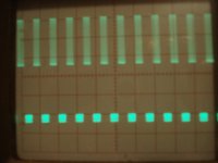
Ok, I put my old 10,000uf caps right at the amp. It helped, but still buzz. See scope1a.jpg and scope2a.jpg - same scope settings as my orginal post.The 3rd trace scope, scope3.jpg is at 5us per div, almost looks like a square wave while fiddling with the trigger on the scope.
When I play music through the amp, at low volume, it sounds a bit distorted with no bass, then as I turn up the volume, the bass kicks in and can go quite loud, but still sounds a bit distorted, almost motorboat kind of sound riding on top of the audio...
Thanks again for your help!
Attachments
It looks like you have to use very long wires from the driver board to the output transistors. Usually you should try to keep connections to transistors as short as possible (parasitic capacitance and whatnot). This could be causing your oscillations, maybe. Solution: Short wires or maybe ferrite beads/cores.
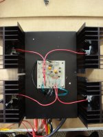
Thanks Rodeodave. I did rewire the amp since the photos above. See attached. I moved the bias wires to top of the amp - the red wires. On the bottom of the amp, I kept the supply wires away (green) from the signal wires (black).
I find the bias and collector wires going to Q7 to be the most sensitive. If I move them around a bit, it does affect the buzz, but never goes away. Moving any of the other wires around has little to no effect.
The kit did not come with TO3 sockets, so I soldered the wires directly to the output transistors - could be a cold solder joint... (I have sockets on order).
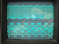
Attached is a scope trace - top trace is +32v rail (same scope settings as above) and the bottom trace is the output of the amp (with input shorted). Scope setting is 100mv per div.
I could move the driver board to underneath the amp and rewire - this would provide the shortest possible path. But I am wondering with a scope trace like that if I have broken something...?
I find the bias and collector wires going to Q7 to be the most sensitive. If I move them around a bit, it does affect the buzz, but never goes away. Moving any of the other wires around has little to no effect.
The kit did not come with TO3 sockets, so I soldered the wires directly to the output transistors - could be a cold solder joint... (I have sockets on order).
Attached is a scope trace - top trace is +32v rail (same scope settings as above) and the bottom trace is the output of the amp (with input shorted). Scope setting is 100mv per div.
I could move the driver board to underneath the amp and rewire - this would provide the shortest possible path. But I am wondering with a scope trace like that if I have broken something...?
Attachments
I hate to say that, but your wiring looks like it's contributing to the problem. Making all the connections with parallel pairs of wires may seem like a good idea at first, but in reality it's adding capacitances everywhere. I don't know how sensitive the A40 circuitry is to such parasitic capacitances, but that's usually one way to get an amp to oscillate.
Keep the wires coming from the driver board as short as possible, really. Use single wires to exclude the parasitic capacitances. Maybe moving the Zobel network (R20 and C5 at the output) closer to the output transistors helps. And keep the feedback path (R5) as short as possible. If necessary, remove the heatsinks from the case and get the output transistors as close to the driver as possible. Every inch counts. That way you can eliminate all parasitic influences.
How do your voltages check out? Nelson mentions a couple test points in the A40 article, under Final Test.
Where does the oscillation first appear? Short the input to ground, and prod around with the oscilloscope probe. Work your way from the input to the output transistors. Check the bases of all transistors, what do you see? Any idea how fast the oscillation is?
Edit: The envelope of the top waveform in the last picture looks like a typical charging/discharging capacitor, what's the time resolution of the scope in this shot? Where did you put the oscilloscope's ground clip for that measurement?
Last edited:
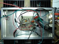
Rodeodave, many thanks you are absolutely right! I mounted the circuit board under the amp and rewired with single wires as short as possible. See pic. The alligator clips are to a couple of local supply capacitors as suggested by Mr. Pass.
I can almost get the buzz to be inaudible by fiddling with the wires.
It is really sensitive, particularly the wires going to the bias adn collectors on Q7 and and Q8. I suspect one of my issues is that I don't get a good connection on the collectors of the output transistors as I can only screw down the lug with a nylon nut that are easily stripped. Waiting on real TO3 sockets.
I will check the voltages again, but I do remember them being what was specd under Final Test when I tested them eariler.
See scope trace 4a and scope 4b. Input shorted measuring the output across the speakers terminals, probe on red, ground on black.
4a is at 10ms per div and 100 mv per div. Noise seems to be 500mv peak to peak. 4b is the same except for .2us per div. That oscillation is in the Mhz range. Do you think getting some ferrite beads would help get rid of that?
What's the trick with the wiring? I am using regular 18 awg hook up wire. Should I be using different wire? Should I move the R16 thru R19 closer to the emitters of the output transistors?
Again many thanks for your assistance!
Attachments
Pass DIY Addict
Joined 2000
Paid Member
Hey Mitch,
What wire gauge did you use to connect your power supply to the amp boards? I would recommend a minimum of 14ga, perhaps 12ga. Also, how did you connect your output transistors to the heat sink without the use of TO-3 mounting sockets? If the transistors are not coupled to the sinks, there can be all kinds of trouble as they heat up.
I'm sorry that I don't have the original papers that detailed the error on the circuit board (you need to cut one trace - its very easy to do with a razor knife), but if you compare the traces on your PCB with Fig 9/10 in the PDF for the a40 project, you'll find it. My boards are buried so deeply in the amp chassis that I can't easily get them out to photograph them.
Eric
As I recall, the "error" was simply that different Jfets have different
pinouts, and you had to be careful that yours was wire the same way as
the schematic. If you are unsure, then replace the Jfet with a 10K resistor
and see what happens.
Wire gauge is not the issue here and will not have much effect on the
oscillation. Actual layout and proximity of wires and the details of grounding
are more likely to be culprits.
Hey Eric.
I used 14/3 for a run of <4 feet from the PS. 20 years ago, I was going to put it all in one chassis/case. Today I like mono block look with cages, but did not think through the PS consequences. I have put supply caps (1 x Nichicon 4700uf 50v KWM per rail, per amp - more?) local at each amp as mentioned by Mr. Pass. I have some bypass caps as suggested on your site. I also have the snubbers, but have not installed them yet.
The Old Colony kit came with these small molded nylon insulaters - style D here: http://ca.mouser.com/catalog/catalogUSD/643/1608.pdf and using a mica insulator with grease. I soldered to the base/emitter and used a lug that attached underneath the screw, secured with a nylon nut (that always stipped) for the collector - I don't think there ever was a good connection there.
This was before I found your site and this site. Since I have the same heat sinks as you do, I got the sockets and sil-pads from your a40 build site. Thanks for that.
Before I go any further, I am going to remount all the output transistors. And then rewire. Given my scenaraio, the wires from the board to the bias of Q7 and Q8 seem pretty sensitive, I was going to rewire that using a thick gauge shielded cable with the one end grounded at the star for that amp. Not sure if this is necessary of just some lower capacitance cabling then the 18 awg hook up wire I have - seems to break too easy and looks cheap.
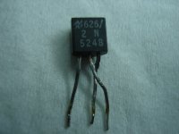
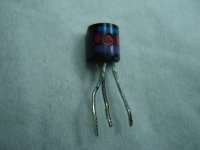
I also need to find out the proper pinout of the attached JFET. I am wondering if anyone has the datasheet or maybe knows the manufacturer. Right now, I can't be sure it is not plugged in backwards. Maybe I just will get some new ones. I will try your ohm meter procedure and see what I get.
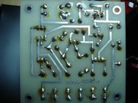
Also attached is a pic of one of the Old Colony boards. I think maybe from 90 or 91 when I got them. From what I can see, it seems that the board matches the diagram in the Pass a40 PDF. Maybe I am missing something?
Once the transistors are mounted and hooked up proper, I am going to take Rodeodaves advice and recheck all of the circuit volatges and probe around at the base of the transistors to see if everything checks out or not. Maybe then I can figure out where that really high frequency oscillation is coming from (I do several wireless computers in the house), but I do notice the oscillation is both on the amp output and power supply rails).
Thanks again for your a40 build site!
Mitch
I used 14/3 for a run of <4 feet from the PS. 20 years ago, I was going to put it all in one chassis/case. Today I like mono block look with cages, but did not think through the PS consequences. I have put supply caps (1 x Nichicon 4700uf 50v KWM per rail, per amp - more?) local at each amp as mentioned by Mr. Pass. I have some bypass caps as suggested on your site. I also have the snubbers, but have not installed them yet.
The Old Colony kit came with these small molded nylon insulaters - style D here: http://ca.mouser.com/catalog/catalogUSD/643/1608.pdf and using a mica insulator with grease. I soldered to the base/emitter and used a lug that attached underneath the screw, secured with a nylon nut (that always stipped) for the collector - I don't think there ever was a good connection there.
This was before I found your site and this site. Since I have the same heat sinks as you do, I got the sockets and sil-pads from your a40 build site. Thanks for that.
Before I go any further, I am going to remount all the output transistors. And then rewire. Given my scenaraio, the wires from the board to the bias of Q7 and Q8 seem pretty sensitive, I was going to rewire that using a thick gauge shielded cable with the one end grounded at the star for that amp. Not sure if this is necessary of just some lower capacitance cabling then the 18 awg hook up wire I have - seems to break too easy and looks cheap.
I also need to find out the proper pinout of the attached JFET. I am wondering if anyone has the datasheet or maybe knows the manufacturer. Right now, I can't be sure it is not plugged in backwards. Maybe I just will get some new ones. I will try your ohm meter procedure and see what I get.
Also attached is a pic of one of the Old Colony boards. I think maybe from 90 or 91 when I got them. From what I can see, it seems that the board matches the diagram in the Pass a40 PDF. Maybe I am missing something?
Once the transistors are mounted and hooked up proper, I am going to take Rodeodaves advice and recheck all of the circuit volatges and probe around at the base of the transistors to see if everything checks out or not. Maybe then I can figure out where that really high frequency oscillation is coming from (I do several wireless computers in the house), but I do notice the oscillation is both on the amp output and power supply rails).
Thanks again for your a40 build site!
Mitch
Attachments
Pass DIY Addict
Joined 2000
Paid Member
Yep, your board has the trace error that needs to be fixed. Check out the PDF that I emailed to you - I also added it to my a40 web site. My wife makes fun of me for being a packrat, but you never know when you'll need something like old documentation ;-)
The TO-3 sockets that I have look like either A or C in the link you provided. I also see what you meant by mounting them without the sockets (mounting method E on the left of the link you posted). The best advantage I can think of for using the socket is to avoid overheating the transistor when soldering the wire leads.
Eric
Last edited:
Pass DIY Addict
Joined 2000
Paid Member
As I recall, the "error" was simply that different Jfets have different
pinouts, and you had to be careful that yours was wire the same way as
the schematic. If you are unsure, then replace the Jfet with a 10K resistor
and see what happens.
Wire gauge is not the issue here and will not have much effect on the
oscillation. Actual layout and proximity of wires and the details of grounding
are more likely to be culprits.
Thank you for the tips, Nelson! I was really surprised when I discovered the different pinouts for the JFETs when I was building mine. I spent a great deal of time with wire layout to get my amp to be silent. Experimenting with this take a little care, though. I learned a good lesson about keeping the alligator clip leads on my power supply away from one another - I had an interesting shower of sparks one day and a few small holes in the rug as a result...
Eric
Thank you Eric! Wow, I would have never found that - I am so grateful. I have posted your PDF here as well.
Mr. Pass, thanks so much for your continued advice. As evidenced by sharing photos, my electro-mechanical skills aren't the greatest. Especially compared to other builds on this site that go way beyond professional - I am in awe. What a great community!
Cheers!
Mr. Pass, thanks so much for your continued advice. As evidenced by sharing photos, my electro-mechanical skills aren't the greatest. Especially compared to other builds on this site that go way beyond professional - I am in awe. What a great community!
Cheers!
Attachments
Pass DIY Addict
Joined 2000
Paid Member
Nelson, the "reverse effect" is curious...
I made the modification to the board as described in the PDF and mounted the transistor as indicated in the article (B,C,E as labeled) and things work (and measure on the scope) quite well. Bandwidth is about 240kHz, and square waves remain nicely square up past 50-70kHz.
Perhaps Mitch is experiencing multiple problems all at the same time
Eric
I couldn't tell from the pictures but are your heat-sinks grounded to their chassis and are the amp chassis grounded to the power supply chassis? Nelson made it a point in the original article that the heat-sinks must be grounded.
Craig
Craig, thanks for asking. Yes, the heatsinks are grounded to the amp chassis and the amp chassis is grounded to the power supply chassis. Power supply chassis is is tied to star ground (i.e. earth gnd.).
I am working through multiple problems - not good connections to transistors, which is now fixed. Circuit board needed to be modified as above - done. And now I am hooking it all back together with short leads as per Rodeodave, local supply caps per Mr. Pass, and then the wild card JFET is last.
Will know the outcome this evening.
Cheers, Mitch
Pass DIY Addict
Joined 2000
Paid Member
- Status
- This old topic is closed. If you want to reopen this topic, contact a moderator using the "Report Post" button.
- Home
- Amplifiers
- Pass Labs
- a40 oscillation