Attached is a pic of a new Class A amp prototype inspired by my work with the "Half Nelson" amp described elsewhere in the Pass Labs forum, and also as a result of a little email back-and-forth between me and Papa after last year's Burning Amp. It solves a few of the problems I encountered with the Half Nelson, at the cost of a tiny bit of extra complexity (actually, the parts count is probably very similar between the two - I'd have to open up both schematics and do a head count).The new design also eliminated a lot of nasty coupling caps.Schematic will follow when I get the thing powered up and nail down the bias values. I'm also working on a version of the Half Nelson using the Semisouth R085 jfet, but that one is on hold for a while, as this amp may be easier to spit out. I'm also working on a tube-type design using an R085, but that will be the subject of another thread. Burning Amp should be interesting this year...
Attachments
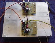

Attached is a tentative schematic for the Le Mutant. I have both channels running thermally stable (one at a time) with a bias current of ~1.5A. Even with such a large heat sink, it gets real hot, so there will most likely be a toned down DC fan to augment cooling. I've made no attempt to pre-select or match output/bias FETs, so each channel needs individual tweaking for both the bias current and so that the input differential stage is in balance with no signal. Right now, I'm getting about 18mV of output offset for each channel, not too bad for the first attempt. The resistors to tweak are R4 and R5. A 2.2K resistor was added in series with the collector of Q9 to reduce its power dissipation. It still runs considerably hotter than Q8, unbalancing the mirror somewhat. A subsequent version of this amp will use some nice Fairchild TO-126 devices coupled to a common heat sink. I will also investigate what can be accomplished by selecting/matching Q4-Q7. I may also add a pot to help tweak in the bias.
The 2200uF capacitors on each rail are only the local bypassing. The main filter caps will be much more massive.
I still have some work to do before I unleash this thing on some speakers, but it won't be too long.
The 2200uF capacitors on each rail are only the local bypassing. The main filter caps will be much more massive.
I still have some work to do before I unleash this thing on some speakers, but it won't be too long.
Attachments
I took the mutie off the big heat sink. As of tonight, both channels are on an aluminum heat spreader plate with a pair of microprocessor coolers on the back side to pull heat out. It's a much more compact setup. Next is to complete the new amp modules incorporating the changes I mentioned in the last post, as well as matching up some output devices. I should be powering this baby up in the next week or so.
 )
)Jacco, you're easily amused...
Q4 and Q7 are indeed mounted right next to their respective output devices on the heat sink. Bias was stable when I fired up the first revision of this circuit. In the next revision, I have added a pot to tweak in the bias/balance, and have changed the mirror transistors to TO-126 devices on a common heat sink, in addition to a resistor to help equalize power dissipation. I need to sit down and sort some mosfets before I can finish populating the next revision boards. I'm expecting that the better matching will improve DC offset a bit. The next schematic will follow when I have the boards populated and tested.
This one should be finished in time to play at Burning Amp.
Passing-for-Pass designs for this year's Burning Amp will probably include the one posted here, the "SiC Puppy" (once I do the heat spreader/microprocessor cooler routine with it as well), and a revved-up version of the "Half Nelson" with a higher VCC supply and a fan on top to prevent melt-down. I have tube amp designs in the works as well, but that's another thread, another forum. I actually had another inspiration for a Pass-type design last night before I dropped off to sleep, but I'm putting that one on hold so I can get something finished.
The stuff I bring to Burning Amp may consist of engineering sculptures lashed up on a piece of plywood for expediency's sake (Papa does it, why can't I?). In which case, god/dog help the inquisitive fingers that attempt to palpitate the Sic Puppy - 300+ volts (with some authority behind it) is no joke...
Last edited:
This afternoon, I sorted a bunch of IXYS 200V, 0.17 ohm P-channel fets to serve in the output stage. I'm hoping they will be a better match to the IRFP240 than the usual 9240 types. Once I go through my IRFP240s the same way, I can sort the driver fets. The output fets are strapped gate-to-drain, and labeled with the Vgs for a bias current of 1.5A (bench supply in constant current mode). The power devices are bolted to a fan-cooled microprocessor heat sink during characterization so that thermal drift is held to a minimum, and I can get a stable value for Vgs relatively quickly. The driver transistors will be sorted and labeled for 10ma drain current using my usual fet sorting jig. Once I have the numbers on everyone, I'll start pairing up driver and output fets.
Here's a picture of the new modules for the mutant bolted to a common heat spreader, with CPU coolers attached on the other side directly over the output devices. One channel biases up ok, the other has a problem which is likely to be a cold solder joint or a solder splash, as there's not a whole lot to go wrong with the circuit. I have to take the whole thing apart anyway to put some thermal grease on the CPU coolers, so its not a biggie to get the bad module sorted out at the same time. I'd say I'm close to getting some tunes out of this thing, even if it's just using a bench supply. I suspect that this amp will likely show up at Burning Amp with the same sort of impromptu setup I'm using for the "Half Nelson" (well, maybe a little prettier, but not by much).
Attachments
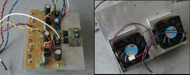
I found the problem in the bad channel (open solder joint), and now both channels bias up the same. The CPU coolers definitely do their bit in reducing the temperature of the heat spreader.They're not really all that loud, even at full blast. The bias current is a little over my optimum (1.6A-1.7A vs. 1.5A). As soon as I get that tweaked to my satisfaction, it's tune time, even if I have to use a bench supply. This amp will get the 2 X 20V Antek toroid from my "Half-Nelson", which will in turn get one of the toroids I scored from Papa at the first Burning Amp in 2007.
Attached is the mutant that will be slouching its way over to this year's Burning Amp. I ended up with selected IRFP9240s instead of the IXYS P-channel guys I wanted to try, as I was able to select a pair of the IRFs that were a closer to the IRFP240s I had on hand than any of the IXYS fets. I ran both channels of the amp using my bench supply at work, and the sound was OK, but there were some issues with asymmetric supply rails, as the amps were really taking more current than the bench supply could handle without going into limiting on one side. I'll expect better results with a solid DC supply - in the works.
Attachments
Le Mutant is going into a case raped/gutted from an old server SMPS - the case was smaller than I remembered, but the CPU coolers make the gain modules small enough so that everything will fit inside. This puppy may be up before the weekend's over. I wanted to fit the "Sic Puppy" inside this case, but the overall emphasis in big iron on that project won't let me. That one will probably end up looking like the "Half Nelson", but with a little more elegant implementation, thanks to more CPU coolers and some Corian.
Pictures of the Mutant will follow later today when I'm finished wiring the thing up and doing a power-up test. It's in an industrial case that used to belong to an old server supply - boring but functional, and PD small for a class A amp good for ~30W/channel.
Last edited:
Le Mutant went to work with me. The thermal imager reports an output device case temp of ~80C, which means that the junction temp is probably over 100C. A lot of this is do to the insufficient maens for heat removal inside the chassis. The CPU coolers I chose to go on the heat spreader do a good job of pulling heat off the spreader, but then they sort of spray it around inside the chassis. I can put up with this situation long enough for a BA demo - what's Buring Amp without a hot amp, anyway? I may add another fan tie-wrapped to the front panel grille to pull some more hot air out - noiser but cooler. I have solutions coming that will allow me to better get the heat out of the chassis, but for the time being what I have is good enough to survive some demos.
I'm very happy with the square wave response - attached is a photo of the overall square wave response.
I'm very happy with the square wave response - attached is a photo of the overall square wave response.
Attachments
- Home
- Amplifiers
- Pass Labs
- "Le Mutant" Class A