something in line with this : http://www.diyaudio.com/forums/pass-labs/201655-lamp-simple-sit-amp-50.html#post2998542
I'm not saying all values are adequate for your cause , but what's important is principle
I don't have depletions , so I can't help more , except with dry datasheet based conclusions
I'm not saying all values are adequate for your cause , but what's important is principle
I don't have depletions , so I can't help more , except with dry datasheet based conclusions

Buzzforb,
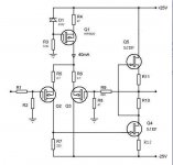
Your pic was supposed to look like smth attached. SRPP.
In this case top tr do not need to be of depl type, ench SJEP will be
equally good.
But remember, that this circuit with SemiSouthes will have high output impedance =current drive. And you will not achieve muF with this vertical positioning of one on top of the other - only if you "disassemble" the pair.
Those SS will require volt FB to have sufficiently low output imp.
Smth along the lines of post by Knutn -also attached.
Attachments
Thanks Steven. Why does the top resistor need to be .9 vs 1R? Isn't this the bias setting resistor for the top fet? If i take the signal from above this resistor, do I have a Mu Follower? I must admit that I do not understand the "disassemble" part, but that is not shocking. I guess feedback and output impedance are a reason Nelson uses the LTP input in his FW amps, although i thought that Zout would be reasonable. I am going to measure curves for the R085 and start doing some actual math today. May also consider using FQA up top as it has higher Yfs than R085 and that should help with Zout, correct?
One more thing. The reason I used a voltage divider on the R085, is that Nelson had stated in other threads that stability of the bias of the upper fet was problematic, even with depletion devices. This was not a direct comment from him, but extrapolated from what was stated about smaller Jfet cousins, like sk170.
One more thing. The reason I used a voltage divider on the R085, is that Nelson had stated in other threads that stability of the bias of the upper fet was problematic, even with depletion devices. This was not a direct comment from him, but extrapolated from what was stated about smaller Jfet cousins, like sk170.
Last edited:
as I wrote few times - try to find (buy , steal , borrow ) book called How to gain gain_A Reference Book on Triodes in Audio Pre-Amps
interesting reading , back to the roots and up to the sky
goooogl is your friend
then you'll learn difference between mu, srpp etc.
for output impedance of mu follower , ratio of these two resistor in totem is dominant - over xconductance , of used part
interesting reading , back to the roots and up to the sky
goooogl is your friend
then you'll learn difference between mu, srpp etc.
for output impedance of mu follower , ratio of these two resistor in totem is dominant - over xconductance , of used part
Last edited:
")
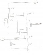
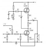
If you want to stay with just 2 tr. SRPP, then you can add local volt FB
to reduce output imp.
See attach.
This shunt VFB will also reduce input imp - R5 need to be of several KΩ.
R6 will set the gain - make it tens KΩ.
R4 will set the output volt center/midpoint, like +25V. Pot in megaohms range (or two resistors in series).
C1 needs to be as high as possible, 10µF or more, and of a good quality.
R3 like 30-50 KΩ.
With Q1 being SJEP, R2 value can be selected by listening. You can start
with zero and progress towards ~0.4 Ω. It will affect distortions, speaker damping, gain.
Without speaker, this circuit will need equivalent resistor of speaker Ohms value for bias to function properly.
Your Fairchilds do not belong in SRPP.
Attachments
Interesting. Unfortunately I do not have SJEP, that is why I was working with SJDP. If using enhancement mode device on bottom, LTP becomes overly attractive for what it adds. I guess it reasonable to think that non LTP input may sound better since a gain stage is dropped. Only testing will tell. Is R4 sets bias, but is it also functioning as Schade feedback? Could throw this together with FQA on bottom or maybe even lateral 2sk. THey are the only enhancement devices I have. THanks. THis gives me something to study and build. ZM pointed me to some good reading. I will be playing with this for a while I think.
Will this work? Lm317 based voltage regultor for higher current than other wise possible with just regulator. MAy have to parallel the fets as this psu could see up to 4-5A at 35-35V. Just trying to use what I have on hand. It is not for scehmatic above and does not include gate stopper or protection diode. THought it might need a resitor in front of lm317 for current protection, but unsure.
Attachments
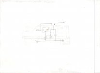
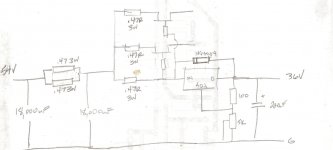
Been using crappy Express PCB software too long. Rarely use the schemtic editor, just pcb drawing tool. Do I need zeners to protect gates?Ant other improvement suggestions. I figuring this will max out at about 4A. May change the fet resistosr to parallel .47R for more current capability. Any improvements possible or is ths decent.
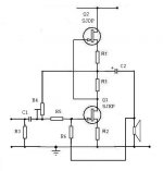
And if you have to stay with SJDP only, you just combine the two sketches
I have posted into one attached.
The new negative voltage reference will set both JFets to the selected current bias, pot in the voltage divider will set the output node to the ~half of the supply voltage. Just find the lowest value for R2, that will work for
your speakers and your ears (again, it's a balancing act). Here R4 will be tens KOhm.
Attachments
- Status
- This old topic is closed. If you want to reopen this topic, contact a moderator using the "Report Post" button.
- Home
- Amplifiers
- Pass Labs
- SS 120R085 Depletion Mode Jfet