Helps with gain too, correct, which is a valuable commodity in this particular arrangement, from what I have learned. I have a computer based distortion rig that i will haev to hookup and figure out, so that all this can be tested and made official whwn all is said and done. I have orignal layout ready, and will probably try to throw together this weekend.
Got two 10" x 12" sinks for old fashioned testing method. Trying to do the quick route with curve tracer, but this part pushes the envelope a little bit.And you don't need an oven (your wife may force you to clean it afterwards), you need a good size heatsink for measurements.
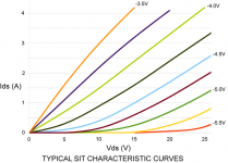
I am going to push it a little further. Just thought it was an interesting set of curves. I think tha max i can push the tracer is 32V and about 2.5A. I can pussh the current again by bypassing the limiter, and see what that brings. Looks a lot like the ZenV8 article graph for the LU, difference being that this thing can take the heat.
THats it. It has its limitations in terms of high current/voltage testing, as you can see with the R085 Jfet. I think it is possible to make changes and beef things up a bit, but i dont plan on trying until after i finish batch testing the GB. Exellent buy and ha matched the old method in terms of accuracy. Gives you the advantage of matching an entire curve vs a single point...big advantage.
Well, I've been digestiing some of that... Looks very much like the operation I think we are interested in... I even took it upon myself to sketch some extrpolated lines further out...
I think it is interesting that the graph buzzforb is producing is the area below the graph in the data sheet. (Great work there buzz) The data sheet does not show this "triode" like behaviour!
So, can we find some ideal operating point in there somewhere? I have 2 parts and a doner Heat Sink, I suppose I can find 2 50W 1 ohm's
Attachments
I think I am going to try pure SE first, then move to SRPP. To me, the graph looks a little like the Sit graph. Gonna try with triple 22R 50W as Rd. No Rs and fixed bias. Rails will be a measly 27V. Gonna see if i can locate sweet spot for this particular device and then move to SRPP. Starting with -4.9V Vgsand about 1.8A. Moving slow and trying to learn.

Exactly! The resistor string is from this thread. Steven recommended .1 ohm lower on top resistor...just like amp camp amp. Never thought of it that way, but the P3 analogy is perfect. THanks. Let me know if you want other measurements. Gonna set the curve tracer up to do 4A, but it reduces available voltage. Did you see the last measurement. Greater voltage makes a significant difference in the positioning of the curves. From the couple i have tried, 4.8-5.3 seems to be a nice starting spot. Little comparison for ya.
Attachments
I beleive the shifting of the output point, from top to bottom of the 2 ohm string, will actually make more or less current source or push-pull output. Analagus also to the gain adjustment of the Aleph current source and the pot in the PLH. I think he said we would like a choice or something.

Yes the last measurements still didn't quite get what I was totally wanting to see though, but, it still looks good. Somehow, I can't beleive you're the first to find this? And like I said, it was right under our nose's, just not in the data sheet.
I notice some reasons for apprehension though. For instance, we brave Diy'ers probably want to run this thing at 35-45W dissapation. I don't know if that's such a good idea. I know about the reputation of SiC and all. The plastic package will probably survive some rediculous heat for a while too. But it kinda looks like this is a small die in a big package. Something we usually want but don't get but, in this case, that might mean 25W max dissapation? the theta j only spec'ed at max 1.1 C/W isn't impressive either.
Also, if you want to self bias, the 2 ohm thing might be a killer???
This is where i get lost as well. Then again, not so different from Sit graph above.That is the main reason I am trying simple resistor loaded version first. I can measure gain rather directly that way and then see how SRPP compares. I have also thought of cascode on top but seems like a waist. Nelson had the DeLite biased pretty high, 80V-1.8A. I know bulb dropped a lot, but still should be pretty wamr area of operation. Nemesis article he seemed to suggest 40W. I will have mine finished tomorrow, hopefully. I remember Broskie calling the SRPP an impedance multiplier. Wonder what impedance it multiplies? Oh well. Tomorrow.
- Status
- This old topic is closed. If you want to reopen this topic, contact a moderator using the "Report Post" button.
- Home
- Amplifiers
- Pass Labs
- SS 120R085 Depletion Mode Jfet