I have posted on here wondering about the capability of this extrusion when used for the F-5. My current build is using them and is not yet finished, but another builder I know has completed a F-5 using these sinks. They appear to be 6 inch sections, and I inquired about them and there performance. He said his prior build which used the Conrad sinks in comparison to this was basically the same. He said it didnt seem to be any hotter.
I will of course comment further as I complete this new build, but htis news along with several other builders who have sent me PMs indicate the same.
These sinks are a bargain and apparently adequate for F-5 usage!
Cool, they only run 25.25 USD for each 6 inch piece, and 33.67 for each 8 inch piece.
Russellc
did your recent sinks come with any deformation? I have a pair of 5 inchers that arrived with some curvature along the 10.08.... I managed to reform them to something resembling 'flat' with c-clamps (that flange on the ends came in handy) and shims wedged in the middle. It would be nice to avoid that fiasco in the future, since I have plans to use a smaller pair for an I/V, so it matches the amp..
half a millimeter or less over a 10" profile would be ok
I would not like it to be more than a millimeter
I once suggested to 'alter/modify' the plastic edges of the transistor
makes the plane portion of the transistor narrower
on a non smooth surface, less width means better/closer contact
but its minor
besides, many modern isolation pads are soft enough to take care of it
perfectly plane is only possible with machining
but a question whether it stays plane forever
btw, because of all this I also have my doubts about the use of large surface 'heatspreaders'
unless its sanded down to match
but a difficult task
oh, and do you also remember to check the backside surface of your transistors")
I would not like it to be more than a millimeter
I once suggested to 'alter/modify' the plastic edges of the transistor
makes the plane portion of the transistor narrower
on a non smooth surface, less width means better/closer contact
but its minor
besides, many modern isolation pads are soft enough to take care of it
perfectly plane is only possible with machining
but a question whether it stays plane forever
btw, because of all this I also have my doubts about the use of large surface 'heatspreaders'
unless its sanded down to match
but a difficult task
oh, and do you also remember to check the backside surface of your transistors
Hi tinitus
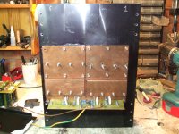
I had mine 12 X 16 machined after the extrusion as is normal that the surface is not flat after the extrusion
To get the heat spreaders to match the surface of the sink is not that difficult it just takes loads of time patience and elbow grease
Just get the spreaders as flat as you can starting with coarse emery cloth stuck on a flat surface and then down to 600 grain then polish the lot so is like a mirror and then start rubbing the heath spreaders on the heath sinks with carbide paste then paint scratch remover and at last bicarb of soda.
Once is all done and really clean the heath spreader stick to the heats sink as if it was magnetised (obviously as you making a vacuum as copper and aluminium magnets do not exist in this continuum).
Say about 10 hours work.
Graphite thermal paste when you bolt the 2 together.
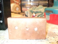
Main advantage is that I can use trough bolts with the heads buried in the cooper spreaders and clamp the mosfets with those
Gives far beter torque on the nuts securing them than if you where using the single screw and if you strip a tread just knock out the bolt and refit.
I am using Kerafoll and from the graphs in the data sheet the thermal resistance drop with increased pressure.
With about 200 W thermal load on the sinks they run at about 42 C with the mosfets at about 60 / 62 C on the top of the case.
Picture 1 of heat sink & fitted spreaders and 2 of details on how bolt are fitted
http://www.diyaudio.com/forums/swap-meet/182480-holco-mfr-15ppm-2w-sale.html
I had mine 12 X 16 machined after the extrusion as is normal that the surface is not flat after the extrusion
To get the heat spreaders to match the surface of the sink is not that difficult it just takes loads of time patience and elbow grease
Just get the spreaders as flat as you can starting with coarse emery cloth stuck on a flat surface and then down to 600 grain then polish the lot so is like a mirror and then start rubbing the heath spreaders on the heath sinks with carbide paste then paint scratch remover and at last bicarb of soda.
Once is all done and really clean the heath spreader stick to the heats sink as if it was magnetised (obviously as you making a vacuum as copper and aluminium magnets do not exist in this continuum).
Say about 10 hours work.
Graphite thermal paste when you bolt the 2 together.
Main advantage is that I can use trough bolts with the heads buried in the cooper spreaders and clamp the mosfets with those
Gives far beter torque on the nuts securing them than if you where using the single screw and if you strip a tread just knock out the bolt and refit.
I am using Kerafoll and from the graphs in the data sheet the thermal resistance drop with increased pressure.
With about 200 W thermal load on the sinks they run at about 42 C with the mosfets at about 60 / 62 C on the top of the case.
Picture 1 of heat sink & fitted spreaders and 2 of details on how bolt are fitted
http://www.diyaudio.com/forums/swap-meet/182480-holco-mfr-15ppm-2w-sale.html
Attachments
I am using Kerafoll and from the graphs in the data sheet the thermal resistance drop with increased pressure.
hmm, yes, Kerafoil being relative thick and quite soft, that sounds logical
but I would be careful not using too much pressure
could there not be risk of cracking the 'plastic' casing
hey, seems you have put a lot more work into it than meets the eye
I just delivery of a set of these in the 8in length for an AJ. They've been sitting on the bench awaiting delivery of some other parts and a design plan for a chassis. At a glance there doesn't appear to be a curvature problem. Would have preferred Seiferts but for the price you can't beat these.
D
D
Anodised job done localy
They aply a standard charge for the job
2 heath sink =£40
10 heath sinks= £40
If you go for the anodised make shure you have a couple of holes drilled on the sink where you want them as they need a place where to make a good electricall conection for the process to take place.
I have made the mistake not to do so and ended up with same marks exactley where I did not want them.
Yes tinitus loads of work and probably once done I will re start all over again
The sound I got out of the mule more than justify the time invested in it and is also loads of fun.
Yes maybe it looks a bit srufy and the paint job is crap (give me a paint brush and I became realy dangerous) but I have made it myself some one would call this DIY I think
Small curvature on sinks without heat spreaders would not matter much
But you could ceck with a straigt edge (like stanley knife blade) shine same light on the back of it and have a look.
To cek the whole sink you need some sort of realy flat surface Glass /Granite and a bit of oily ink rub the sink on the surface and the ink shows the hi spots.
But you could ceck with a straigt edge (like stanley knife blade) shine same light on the back of it and have a look.
To cek the whole sink you need some sort of realy flat surface Glass /Granite and a bit of oily ink rub the sink on the surface and the ink shows the hi spots.
Russell,
Where did you get those kerafols?
D
member zhoufang right here on DIYaudio!
Russell
- Status
- This old topic is closed. If you want to reopen this topic, contact a moderator using the "Report Post" button.
- Home
- Amplifiers
- Pass Labs
- 10.080 inch HeatSinkUSA F-5 performance