Want to experiment with a choke input filter(inductor after rectifier bridge) compared to PI filter. For 60Hz mains power I found the formula L(henries) = E(volts) / I(milli- amps) x .88. This gives the absolute minimum choke size.
My question is how many amps can I expect from a 30 Volt DC supplied SOZ?
Has anyone tried a Choke input SOZ? Or can share the general difference one can expect betwween choke input VS PI?
Thanks in advance for any who respond.
For a 50 Hz supply the formula is L=Volts / milli-amps X 1.06
My question is how many amps can I expect from a 30 Volt DC supplied SOZ?
Has anyone tried a Choke input SOZ? Or can share the general difference one can expect betwween choke input VS PI?
Thanks in advance for any who respond.
For a 50 Hz supply the formula is L=Volts / milli-amps X 1.06
gnomus,
Since you found the formula for critical inductance, I suppose you know that a choke input filter gives a DC voltage of 0.9 times the transformer's RMS voltage while the capacitor input (pi) filter gives a DC voltage of 1.4 times the RMS voltage. In both cases remember that there will be a DC drop across the rectifiers and IR loss in the choke. If your load "goes away" the DC voltage of the choke input filter will go from 0.9 to 1.4 times the transformer voltage, which can cause not nice things to happen.
I have not built SOZ (I have something similar, tho). If by a 30 volt supply you mean +/- 15 volts then I guess you will have about 2.5 amperes per amplifier. (amps per amp") ) As paulb points out, multiply this number by the number of amplifiers you are running.
) As paulb points out, multiply this number by the number of amplifiers you are running.
I use choke input filters on all of my audio amps and recommend them whole heartedly. They are much quieter electrically and there is less audible noise from the power transformer. Inrush current is greatly reduced also. Another plus.
Happy listening!
Since you found the formula for critical inductance, I suppose you know that a choke input filter gives a DC voltage of 0.9 times the transformer's RMS voltage while the capacitor input (pi) filter gives a DC voltage of 1.4 times the RMS voltage. In both cases remember that there will be a DC drop across the rectifiers and IR loss in the choke. If your load "goes away" the DC voltage of the choke input filter will go from 0.9 to 1.4 times the transformer voltage, which can cause not nice things to happen.
I have not built SOZ (I have something similar, tho). If by a 30 volt supply you mean +/- 15 volts then I guess you will have about 2.5 amperes per amplifier. (amps per amp
) As paulb points out, multiply this number by the number of amplifiers you are running.I use choke input filters on all of my audio amps and recommend them whole heartedly. They are much quieter electrically and there is less audible noise from the power transformer. Inrush current is greatly reduced also. Another plus.
Happy listening!
Hi,
I'm making the SOZ, and am using a pi filter as shown on the web site. The pi configuration has caps going from each leg to the common ground an inductor, and then more caps from each leg to the common.
The thing that seems wierd to me is that on the +Vs side the cap negative is toward the common ground. On the -Vs side, the cap positive is towards the common ground. Is this right?
Also, I think something Grey Rollins mentioned awhile back is becoming clear: I had a transformer with too high voltage.
He suggested a choke supply. I guess he meant to use the .9 configuration vs. the 1.4 pi filter, which would make me end up with a lower output voltage, right?
In the choke (.9) filter, I then follow the inductor with a bunch of caps?
Mark
Ground, positive, and negative are all relative terms. Ground is more negative than the positive rail, yet more positive than the negative rail. An electrolytic cap only cares that the voltage at its positive terminal is more positive than the voltage at its negative terminal. Kind of an electrical analog of the old expression about one man's floor being another man's ceiling.
To use an inductor to lower the voltage coming out of a power supply, it must be first in line after the rectifier. Then come the caps. The voltage rating on the caps should still be high enough to withstand the 1.414 multiplier, though, since if the power supply is ever operated without a load, the voltage will rise up to the same value as a cap input filter.
Grey
Always a Load in a Class A?
In a Class A amp (specifically, the Alephs and Zens), wouldn't the constant bias current constitute a continueous load even if the speaker is disconnected? If that is the case, one would have to disconnect + or - rail from the amp, or one of the FET's would have to fail in order to unload the supply, in which case, you would have bigger problems to contend with.
I guess I wonder if I run a properly sized inductor on the input to the PSU, would the bias current draw of an Aleph be enough to hold the rail voltage to +/- .9 * Vac. How much will the rail voltage depend on the amount of capacitance following the inductor?
Rodd Yamashita
FEThead was the one that spelled it out so I finally grocked it.
Grey, thanks for the clarification. You can really communicate, which I 'm sure you will agree is difficult. I think it helps that the concepts are quite clearly worked out in your mind. I think for a lot of us, our knowlege seems really clear to us until we try to explain it to someone else-then the gaps start to turn up.
I had assumed that L filter was the same as the pi as far as voltage drop. How amazin' that the order of the components makes such a difference.
OK, I found some 5.5mh inductors. They are about .6 DCR
(DC resistance?) vs. about .3 for 2mh. They are 14 Ga.
So... will they heat up too much with 20 amps at 23 volts?
That is about the max I would ever use. Sound like time for Ohms law. Too bad I don't have a clue!
Mark
Rodd,
Yes, the constant current of the class A amp will keep the required load on the power supply. If the speakers become disconnected, no problem. And yes again, it would require a disconnect from the power supply or an FET failing open (short is OK but may over heat the resistors in series with the FET) to cause the power supply voltage to rise. You are correct: if the inductor is the proper size, the class A amp will keep the DC voltage at 0.9 * the VAC of the transformer. (Remember to include about 1 volt drop per diode and the IR drop (resistance) of the inductor when determining the output voltage. See my comments to Mark below.) The amount of output capacitance (after the inductor) will not affect the DC voltage. But the more capacitance the less the ripple voltage.
Mark,
Ohms law is: volts = amps * resistance. In the case you mention 0.6 ohms (DCR is DC resistance - or - ohms) times 20 amps is 12 volts! You will lose 12 volt across the inductor! Then, power is amps * volts. 12 volts * 20 amps = 240 watts! That will get hot!! For the 0.3 ohm inductor: 0.3 ohms * 20 amps = 6 volt drop. 6 volts * 20 amps = 120 watts. So, #14 is a little too small for your application. There are your clues, Mark. Sorry they did not turn out better for you!
Thanks for the replies.
OK, it's starting to become clearer. If my goal is to eventually build an Aleph ~5/60, then I'll have to (or my power supply will) contend with both the + and - rail currents varying (sometime substantially) around the bias current level. Now since this changing current will be drawn directly from the power supply, if I were measure the dynamic voltage drop across the PSU inductor, it would changing with the current. Which in turn would cause my rail voltage to rise and fall with the voltage loss of the inductor, unless... If I have a large enough cap between the inductor and the supply rails of the amp, won't that smooth out the current draw across the PSU input inductor. This would be using a power supply configuration as follows:
Bridge => Inductor => Large Cap in|| => Voltage Rail
or
Bridge => Inductor => PI filter w/Large Cap Last => Voltage Rail
Would this be sufficient enough to smooth the rail voltage fluxuations enough to fix the voltage drop (hence the rail voltage) to a steady state (almost) value.
I will be taking delivery on a Plitron 1000VA +/-33V w/CT and would like to run about 28 or 29 Volt rails at relatively high current.
Thanks all,
Rodd Yamashita
OK, it's starting to become clearer.
If my goal is to eventually build an Aleph ~5/60, then I'll have to (or my power supply will) contend with both the + and - rail currents varying (sometime substantially) around the bias current level. Now since this changing current will be drawn directly from the power supply, if I were measure the dynamic voltage drop across the PSU inductor, it would changing with the current. Which in turn would cause my rail voltage to rise and fall with the voltage loss of the inductor, unless... If I have a large enough cap between the inductor and the supply rails of the amp, won't that smooth out the current draw across the PSU input inductor. This would be using a power supply configuration as follows:Bridge => Inductor => Large Cap in|| => Voltage Rail
or
Bridge => Inductor => PI filter w/Large Cap Last => Voltage Rail
Would this be sufficient enough to smooth the rail voltage fluxuations enough to fix the voltage drop (hence the rail voltage) to a steady state (almost) value.
I will be taking delivery on a Plitron 1000VA +/-33V w/CT and would like to run about 28 or 29 Volt rails at relatively high current.
Thanks all,
Rodd Yamashita
choking on chokes
Hi Rodd,
I am not sure what you mean when you said the transformer would have "+/- 33V W/CT". I think that means a total of 66 VAC with a CT. Based on that lets say your PSU looks like:
- - - inductor - - - cap - - - + rail
[ to gnd ]
XFMR BRIDGE CT to ground amp(s)
[ ]
- - - inductor - - - cap - - - - rail
to gnd
I hope that comes out OK and makes sense. (It did not! See below.)
For an inductor I am going to use as example a Stancor C-2688 simply because I have a couple of them in my power supply and do not have to do any research. These inductors are rated at .010 Hy, 12.5 amps, and .11 ohms each. The formula for critical (or minimum) inductance is: inductance in HY = (output voltage / output current in milliamps). (Or close to this. See earlier posts.) With a choke input filter your outputs will be about +/- 30 volts. (We will treat these as two seperate supplies.) Doing a little math we find that with these chokes you will need to have a minimum of 3 amps flowing to keep the chokes "working". (If you go below 3 amps the voltage will slowly rise as Grey pointed out in another post.) Note that the bridge will have 2 diodes conducting at any one time, and each diode will drop about one volt. So, you are down to about 28 VDC. Now you have 3 amps flowing thru the inductor. Three amps times .11 ohms gives a .33 volt drop across the choke. This brings you down to 27.67 VDC for each rail. Now suppose you pull 12 amps from each rail: 12 * .11 = 1.32 volts drop across the choke. Your rails have now dropped to 26.68 VDC. One volt variation, or about 5% for a four times increase in current. All of this assumes that your transformer voltage remains at exactly "+/- 33V" or 66 VAC total. I do not know anything about the transformer you mention, but a voltage variation of 5% from no load to full load is typical for many transformers. If this is the case, your VAC goes from 66 to about 63, and now your rails will drop to about 26.6 VDC each. And this assumes your line voltage stays the same as you go from 180 watts (3 amps * 60 volts total) to 720 watts. . . . but lets not go there! (Big smile icon here. I can't figure out how to work those things.)
Hope that helps.
BTW, this is a little off topic, but I suggest you put a small (1 uF, not critical) capacitor across the secondary of the transformer. When you turn off the PSU there might be a voltage spike from the collapsing magnetic field in the power transformer, and the small cap will absorb the spike so it does not kill your bridge.
Upon posting this I saw that my attempt at a schematic got mangled big time. (Big frown icon here.) Let me try to explain it: CT goes straight to ground. + from the bridge goes to the inductor. The other side of the inductor goes to a cap to ground and the amp(s). - from the bridge goes to one side of the other inductor. The other side of this inductor goes to a cap to ground and the amp(s). (Big I Hate Computers icon goes here!)
choked on diodes
This a correction to my previous post. In it I said that two diodes would be conducting at any given time. That is true. But since there is a + an a - supply, each supply will be subject to only one diode drop (of about one volt per diode). SO, with 33 volts from the transformer (each side of CT), * 0.9 for the choke input filter gives us about 30 VDC ... minus one volt for the diode brings us to 29 VDC, ... after losing about 0.3 volts in the choke with the 3 amp condition, we are down to about 28.7 VDC, ... and for the 12 amp condition, we are down to about 27.7 VDC. That is per rail. You would end up with about +/- 28 to 29 VDC.
Sorry about the error.
Choke question
I am thinking of building a small SOZ with a choke input filter but
when I run the #'s for say a + - 20v supply at 4 amps it comes up
as a rather large value. In this case wouldn't an iron core inductor
be ok to use and anyone know where to get these at a reasonable cost.
Thanks
bob12345678
I am thinking of building a small SOZ with a choke input filter but
when I run the #'s for say a + - 20v supply at 4 amps it comes up
as a rather large value. In this case wouldn't an iron core inductor
be ok to use and anyone know where to get these at a reasonable cost.
Thanks
bob12345678
Inductor Source
In another thread Mr. Pass recommended the the metal core chokes at www.Zalytron.com These can saturate and the air core chokes do not. You can connect two air cores in series and the total inductance is the sum of them. Another source for air cores is www.Solen.ca
Can someone tell me what happens to a circuit when an inductor saturates? And how can you calculate the right size iron core to avoid saturation?
Thanks to all who reply.
How About Common Mode Chokes?
So,.. The past three days I've been looking high and low to find a way to include power supply filtering without sucking out all of the voltage. I accessed http://www.duncanamps.com/psud2/index.html and downloaded the neat little PSU analysis program (cool, I wonder if I can wear it out by using it too much). Then I went looking for inductors with high inductance and low DCR. I seen soom nice Alepha Cores made with silver foil for a bazillion dollars/oz. Then I ran across the Common Mode Chokes. Not just one or two, but at least a dozen in the US alone. It seems that they are commonly used in circuits ranging from digital data transfer filters running at uAmp levels to 3-phase line protectors operating at hundreds of Amps.
This type of choke can deliver 10's of mH with a DC resistance in the 10's of mOhm range. It appears that the common mode signal on two or more legs of a line are run through the CMC. The choke is just a coil in each line of interest wrapped around a common permeable core (often toroids). The common mode signal builds a field around the core that impedes the common mode signal in the oppossing line. Differential signals pass unimpeded.
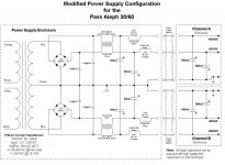
In the power supplies, CMC are usually before the transformer in an RFI filter or line protector circuit. In the few cases I found where the CMC was after the transformer, it was before the rectification. So I thought, what if one were to wind the toroid so that the half waves coming from the bridge's + and - outputs, were seen as common mode noise. We would have an inductor of, say 40mH of inductance, and a DCR of less the 50mOhm, capable of passing 15Amps+, if it's wound with 10 or 12 gauge wire.
I tried to simulate one in Duncan's program and I could run a Transformer with 66VAC w/CT out at 28VDC @ 4amps after filtering. Then when I step the current to 8amps the voltage only drops 1V to just under 27VDC. All this with less then 3mAmps of ripple.
I made a schematic of the circuit I tried to simulate. I hope I don't screw this up as it's my first picture.
Those of you that are current in this stuff and those of you who are just generally in the know, am I barking up the wrong tree with the CMC's or am I on to something, or does Carver already have a patent on this circuit and I need to get a lawyer.
(Well, first try at downloading didn't work at 159kb)
(OK, it's 69kb, and I don't know if it got through or not. It's not in the "Preview Post". I guess that means it didn't work, but I don't know.)
(I give up. I probably have attached three files)
Thanks for the replies.
Rodd Yamashita
So,.. The past three days I've been looking high and low to find a way to include power supply filtering without sucking out all of the voltage. I accessed http://www.duncanamps.com/psud2/index.html and downloaded the neat little PSU analysis program (cool, I wonder if I can wear it out by using it too much). Then I went looking for inductors with high inductance and low DCR. I seen soom nice Alepha Cores made with silver foil for a bazillion dollars/oz. Then I ran across the Common Mode Chokes. Not just one or two, but at least a dozen in the US alone. It seems that they are commonly used in circuits ranging from digital data transfer filters running at uAmp levels to 3-phase line protectors operating at hundreds of Amps.
This type of choke can deliver 10's of mH with a DC resistance in the 10's of mOhm range. It appears that the common mode signal on two or more legs of a line are run through the CMC. The choke is just a coil in each line of interest wrapped around a common permeable core (often toroids). The common mode signal builds a field around the core that impedes the common mode signal in the oppossing line. Differential signals pass unimpeded.
In the power supplies, CMC are usually before the transformer in an RFI filter or line protector circuit. In the few cases I found where the CMC was after the transformer, it was before the rectification. So I thought, what if one were to wind the toroid so that the half waves coming from the bridge's + and - outputs, were seen as common mode noise. We would have an inductor of, say 40mH of inductance, and a DCR of less the 50mOhm, capable of passing 15Amps+, if it's wound with 10 or 12 gauge wire.
I tried to simulate one in Duncan's program and I could run a Transformer with 66VAC w/CT out at 28VDC @ 4amps after filtering. Then when I step the current to 8amps the voltage only drops 1V to just under 27VDC. All this with less then 3mAmps of ripple.
I made a schematic of the circuit I tried to simulate. I hope I don't screw this up as it's my first picture.
Those of you that are current in this stuff and those of you who are just generally in the know, am I barking up the wrong tree with the CMC's or am I on to something, or does Carver already have a patent on this circuit and I need to get a lawyer.
(Well, first try at downloading didn't work at 159kb)
(OK, it's 69kb, and I don't know if it got through or not. It's not in the "Preview Post". I guess that means it didn't work, but I don't know.)
(I give up. I probably have attached three files)
Thanks for the replies.
Rodd Yamashita
Attachments
Hi Woody,
Take a look at this site:
http://www.topmagnetics.com/index.htm
Look at the high current Common Mode Chokes. You'll be amazed at the simplicity of these things. It's no more then a small (<2" in dia for chokes of more then 20mH @ 5.5A) toroid core with a couple of feet of wire wrapped around it.
You could wind it yourself on a bar core, or do a search on the web for Common Mode Chokes. You'll find a lot. I'm sure it would be more then a Solen of the same value.
Good Luck,
Rodd Yamashita
misc. comments
Bob12345678,
You said when you ran the #s on a +/- 20V, 4A PSU you came out with big numbers... What did you get? I came up with (20 V / 4000 mA = .005 Hy) 5 millihenries. Hammond Mfg makes some chokes that should work for about US $23 / ea. (You will need two: one for + and -). Go to: www.hammondmfg.com look under transformers... chokes... 159 series. I think either the 159ZJ or 159ZG will work for you. They also have others that will work, but these are a start.
As for the common mode chokes, the idea is fine but I think the ones Rodd is looking at are for the 100 to 250 KHz range where their power transformers work. (Note that these are in the switch mode PS section of their page.) I do not think they will work at 120 Hz. Unfortunately, at line freqs you need a lot of iron and copper to get a lot of inductance.
Gnomus,
When an inductor saturates it acts just like the wire it is made of. (Same DC resistance) Saturation means that the core is no longer able to absorb energy in its magnetic field. (Similar to a fully charged capacitor.) I think the TMC chokes would saturate in 120 Hz usage, but the ones from Hammond (or others with that much iron and copper) will not saturate. Air core inductors will not saturate but have less inductance per length of wire. Use them after your first L-C section with the "heavy metal" in the first section.
another choke source
Here is a 10 amp 10 mH choke for about $25 (plus shipping)
http://www.surplussales.com/transformers/powerchklist.html
scroll down to cpw-500006001201
I have no connection to this company but I have purchased from them before and they have good stuff.
Happy listening!
Here is a 10 amp 10 mH choke for about $25 (plus shipping)
http://www.surplussales.com/transformers/powerchklist.html
scroll down to cpw-500006001201
I have no connection to this company but I have purchased from them before and they have good stuff.
Happy listening!
Make your own Inductors?
When times are tough and you can't buy - why not make your own air core inductors like the ones below?
http://www.geocities.com/super_bq/soz3.html
When times are tough and you can't buy - why not make your own air core inductors like the ones below?
http://www.geocities.com/super_bq/soz3.html
- Status
- This old topic is closed. If you want to reopen this topic, contact a moderator using the "Report Post" button.
- Home
- Amplifiers
- Pass Labs
- SOZ Choke input filter?