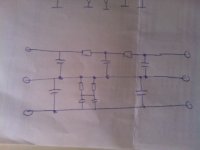
I have just completed making a PCB for my F5 PSU. The circuit I have used is an adaptation of NPs PSU schematic. Instead of CCRCC, I have used CRCCRCC. The values of C being 22000 uF and R being 0.47 ohms.
After soldering all the components, I realized that I have inserted Rs in the positive leg of the supply for both halves as against Papa using the R in the positive rail of the upper half and R in the negative Rail of the bottom half of the PSU.
I want to know if the error committed in my PSU is going to be impacting the supply in any way? is the RC filter going to be effective?
I am enclosing my schematic for reference. Please let me know.
Thanks in advance.
Cheers.
Attachments
IMHO there is no problem electrically with the circuit. It is just two independent DC power supplies wired for +22V, 0V, -22V configuration.
My doubt is if the RC filter is going to be effective only in one leg as a result of my mistake as compared to the original Papa's schematic.
My doubt is if the RC filter is going to be effective only in one leg as a result of my mistake as compared to the original Papa's schematic.
IMHO there is no problem electrically with the circuit. It is just two independent DC power supplies wired for +22V, 0V, -22V configuration.
If you have a bridge rectifier per supply rail, and the supplies are connected together at the output to create the 0V junction, then it will be ok.
My doubt is if the RC filter is going to be effective only in one leg as a result of my mistake as compared to the original Papa's schematic.
From an AC point of view, there is no difference if R is in the + or - rail.
If you have a bridge rectifier per supply rail, and the supplies are connected together at the output to create the 0V junction, then it will be ok.
From an AC point of view, there is no difference if R is in the + or - rail.
Yes, I have a separate winding on the toroid and a separate bridge rectifier per rail. There are two different DC power supplies other than the trafo windings sharing the same toroid core.
That's my question. From a hum point of view, if the RC works, I am good. Otherwise, I was planning to cut the PCB tracks and hardwire the bottom rail again.
Thanks.
Sorry,
Thanks. This is the way the PS is currently configured.
anlive, you have gotten bad advice here. You should mirror the negative part. The resistors must be at the bottom but the PSU will still work but not as intended.
http://www.diyaudio.com/forums/group-buys/117036-power-amp-psu-board-e-g-lynx-amp.html
Send me a message if you want to take a look at the schematics, too large to be uploaded.
http://www.diyaudio.com/forums/group-buys/117036-power-amp-psu-board-e-g-lynx-amp.html
Send me a message if you want to take a look at the schematics, too large to be uploaded.
anlive, you have gotten bad advice here. You should mirror the negative part. The resistors must be at the bottom but the PSU will still work but not as intended.
http://www.diyaudio.com/forums/group-buys/117036-power-amp-psu-board-e-g-lynx-amp.html
Send me a message if you want to take a look at the schematics, too large to be uploaded.
Thanks. I know what you mean. NPs schematic also has a mirrored CCRCC network for each leg of the PSU.
Having committed the error in my PCB, I am trying to find out the impact if at all there is any. The cost of correcting the PCB is cutting the tracks and hardwiring them right or desoldering all the electrolytic.
I buy the AC hum theory and that is should not impact in which leg the RC network is. What is the logic in your view?
Cheers.
You PS will get unsymmetrical with this equivalent circuit. Notice that the negative half will be unfiltered plus two caps doing nothing.
Please refer to the schematic posted by me earlier. They are two separate but identical DC power supplies employing RC filter but connected at the outputs with -ve of one supply and +ve of another supply to make a 0v reference for a +,0,- power supply.
I cannot figure out in what way the RC filter of the bottom rail becomes ineffective. My knowledge is definitely limited and would like to be corrected. Your schematic looks very different from mine.
Cheers.
As long as you do exactly what is shown in drazen's schematic, then everything will be fine. This means modifying your existing schematic, to break the link between W2 and W3 that is shown in your schematic. i.e., the two supplies should be connected only by the link between W6 and W7.
If you stick with your schematic in unmodified form, then peranders's equivalent schematic is exactly right, and, as he says, this is not what you want.
Chris
If you stick with your schematic in unmodified form, then peranders's equivalent schematic is exactly right, and, as he says, this is not what you want.
Chris
You must break/cut the connection at the input just as D has shown.
The two supplies are isolated. They will both filter and give DC with a tiny rounded sawtooth superimposed. The +ve sawtooth should be rounded, I don't know if the -ve will be rounded, or inverted & rounded.
In my understanding, connecting at the output does not change the DC quality of either supply.
I have never done it this way, but you can easily measure the finished PSU (no amplifier/s) to check if both polarities have the same ripple. Do this using a bulb tester first and then direct on line.
As long as you do exactly what is shown in drazen's schematic, then everything will be fine. This means modifying your existing schematic, to break the link between W2 and W3 that is shown in your schematic. i.e., the two supplies should be connected only by the link between W6 and W7.
If you stick with your schematic in unmodified form, then peranders's equivalent schematic is exactly right, and, as he says, this is not what you want.
Chris
You must break/cut the connection at the input just as D has shown.
The two supplies are isolated. They will both filter and give DC with a tiny rounded sawtooth superimposed. The +ve sawtooth should be rounded, I don't know if the -ve will be rounded, or inverted & rounded.
In my understanding, connecting at the output does not change the DC quality of either supply.
I have never done it this way, but you can easily measure the finished PSU (no amplifier/s) to check if both polarities have the same ripple. Do this using a bulb tester first and then direct on line.
Thanks everyone. My mistake. I have not connected W2 & W3 together as I have indicated in my original schematic but followed drazen's schematic.
I have checked AC ripple at the outputs and my Fluke DMM cannot detect any AC outputs.
Finally connected to the amp and works well. No hum.
Cheers.
Thanks everyone. My mistake. I have not connected W2 & W3 together as I have indicated in my original schematic but followed drazen's schematic.
I have checked AC ripple at the outputs and my Fluke DMM cannot detect any AC outputs.
Finally connected to the amp and works well. No hum.
Cheers.
Correction: I measured AC ripple at the PS output. Both rails measure around 35mV of AC, whereas at bridge rectifier, the ripple measures 450mV of AC. There seems to be nearly 1/10th reduction of ripple across the RC network.
The caps are hot (my guess around 35-40 degrees centigrade) and the resistors are quite hot 50-60 degrees centigrade, when the power is being drawn by the amp.
I was about to tell you to buy a new (cheap) DMM, but post18 explained.I have checked AC ripple at the outputs and my Fluke DMM cannot detect any AC outputs.
- Status
- This old topic is closed. If you want to reopen this topic, contact a moderator using the "Report Post" button.
- Home
- Amplifiers
- Pass Labs
- Need help with a F5 PSU mistake