I posted this in the PS forum, but didn't get any responses.
I received a Victoria Magnetics (VM) Transformer in a trade today. The transformer reads "Model #2X14-5005" 117VAC. IT has the following wires:
2x black
2x red
2x white with black stripe
1x green
I assume its a 2x14V 500VA transformer. Any experience on the purposes of each color and wire? With a DMM, there's very little resistance with each pair of wires that are the same color.
I would call VM, but I think they're out of business.
sorry, I don't understand your question
looks very straight forward
with 2x 14V you need two secondary
one secondary black wired, and the other red
one red and black connects together, forming CT/ground
need to find winding direction for correct phasing
black and whites are 2x 117V
in series for 230V mains
paralel for 120V mains
again, need to find winding direction for correct phasing
well, it appears to be so
Maybe you want to take an ohmmeter and find out which leads are
connected to which.

I took a shot at that, I should have posted the results:
0R6 black to black
0R2 red to red
0R2 wb to wb
I get infinite resistance with other combos.
The item looks new, I guess there's a chance there's a problem. It could also be perfect and I don't see the path...
Last edited:
sorry, I don't understand your question
looks very straight forward
with 2x 14V you need two secondary
one secondary black wired, and the other red
one red and black connects together, forming CT/ground
need to find winding direction for correct phasing
black and whites are 2x 117V
in series for 230V mains
parallel for 120V mains
again, need to find winding direction for correct phasing
well, it appears to be so
Maybe straightforward for you...not for me.
I'm happy to plug this thing in and let the chips fall where they may, but I thought I'd ask before I kill someone by mistake.
I've had Anteks before and they are black and red to 110V with the other colors being the secondaries. Now you can see my confusion. I'd have thought the black and reds are 110V and the WB and the ground form a CT 14-0-14.
I know these were popular transformers about 5 years ago, I was hoping someone had direct experience.
I've had Anteks before and they are black and red to 110V with the other colors being the secondaries. Now you can see my confusion.
you should be able to detect the primary windings
they are often thinner, and more flexible
you should be able to detect the primary windings
they are often thinner, and more flexible
-And probably have a higher DCR.
I'll hazard a guess that the black pair is 120V,and red and black/white are the low voltage secondaries.
The Green wire might be an internal electrostatic shield. Is there continuity from the green lead to any of the others? Continuity from the green wire the the transformer case/core?
I'd guess that it's a shield,and can be earth grounded.
Just some Wild A** Guesses.
unless you also have additional low wattage winding as well
you said, 'I assume its 2x 14V'
any good reason for 'assuming'
or it could be anything
like if theres just one primary for 110V mains
which leaves a lot of other options for the remaining windings
first and most its important to find the primary, to be able to power it up, and measure voltage
you said, 'I assume its 2x 14V'
any good reason for 'assuming'
or it could be anything
like if theres just one primary for 110V mains
which leaves a lot of other options for the remaining windings
first and most its important to find the primary, to be able to power it up, and measure voltage
I agree with DigitalJunkie. The red and white/black windings appear to have the same winding resistance so it is logical to assume they are the two equal-voltage secondaries. That would be pretty much confirmed if you can count fewer windings for those colors vs. the black winding (if you are stepping down a voltage, there will be fewer turns).
The part number implies that with 110 VAC input you will get 14 VAC on the two secondaries. Pay attention to polarities!
Please don't just plug a winding into the wall to test! If we got it backwards, you might end up with over 1,000 on another winding, will may cause sparks and damage. It would be best to use a variac, or maybe you could feed a winding with an audio signal (sinewave generator), or even the output of a low voltage transformer, to see what the turns ratios are.
I just took a look at the picture I sent you again and think that this
how the leads are:
2 x Black skinny leads = primary
1 x White lead with Black stripe and heat shrink is the beginning of sec #1
1 x White lead with Black stripe is the end of sec #1
1 x Red lead with heat shrink is the beginning of sec. #2.
1 x Red lead is the end of sec #2.
1 x Green is shield / ground.
I hope this helps. Could not attach photo here.
Just saw your thread.
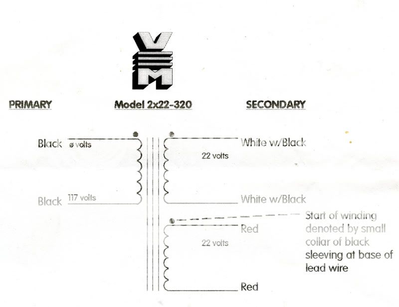
Here's a VM Wiring Diagram. I'm pretty sure all models used the same basic layout.
Thanks, I think this puts the issue in the proper frame of reference.
The schematic matches my toroid. Two questions remain:
- Does it matter which side of the black wires goes to the hot AC lead?
- With a resistance of 0R6, if I plug that into an AC outlet, won't it trip the breaker/fuse? That seems like a very low resistance to go to an outlet (I have little experience with transformers).
Last edited:
Thanks, I think this puts the issue in the proper frame of reference.
The schematic matches my toroid. Two questions remain:
- Does it matter which side of the black wires goes to the hot AC lead?
- With a resistance of 0R6, if I plug that into an AC outlet, won't it trip the breaker/fuse? That seems like a very low resistance to go to an outlet (I have little experience with transformers).
1. no it do not matter.
2. that seems right. mine are about 1.5ohm. but thats 230V trafos.
- Status
- This old topic is closed. If you want to reopen this topic, contact a moderator using the "Report Post" button.
- Home
- Amplifiers
- Pass Labs
- Slightly off topic, but I need help - Victoria Magnetics