Hi to all,
I finished to build my Aleph 30 a couple of weeks ago; now I’m doing some tests and modifications.
The supply voltage of my Aleph is +/- 24 V so the clipping occurs at about 16 Vrms at 1 KHz and at about 14 Vrms at 10 KHz (with a 8 ohms load).
The sound is very good, but the power is not high enough to exclude the possibility of clipping, especially with low efficiency loudspeakers (like mine).
I don’t want to listen to the music and watch at the same time the oscilloscope searching for a clipped waveform, so I decided to equip my Aleph with a clipping detector.
My first idea was to compare the input waveform with an attenuated replica of the output and amplify the difference, but I realized that this was the job of the differential stage of Aleph: so why don’t use directly the signal from the drain of Q2?
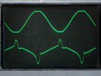
Just before clipping, this signal (that drives the negative mosfets) has a DC component of 3.6 V above the negative rail (gate bias) and an AC component (signal) of about 600 mVp.
When clipping occurs, the waveform has evident spikes like in the picture below.
It is quite normal because the feedback try to correct the deformation due to clipping, pushing up or down the gates of the mosfets, as much as it can.
So positive polarity clipping (negative spikes) can be detected with a threshold comparator, set at about 2.5 V above the negative rail.
The circuit I used is in the attachment below.
The SE555 acts as a comparator (the threshold is internally set at 1/3 of Vcc) and, at the same time, as a one-shot monostable.
The detection threshold can be set adjusting the supply voltage of SE555; this is done by the TL431 shunt regulator (I used this IC because I found a lot of them in a drawer, but one can use a normal regulator as the 7805, configured as an adjustable voltage regulator set).
The trimmer R6 allows to move up and down the threshold; I set it for Vcc = 8.27 V
I tested the circuit and it works fine: it is independent from frequency, load impedance and supply voltage.
It detects only positive polarity clipping of the output voltage, but I don’t think it’s a big problem.
I’ve done some little modifications to my Aleph in order to improve thermal stability of bias, remove ringing and reduce distortion; in the next days I’ll do some measurement; if somebody is interested, please let me know.
Fulvio
I finished to build my Aleph 30 a couple of weeks ago; now I’m doing some tests and modifications.
The supply voltage of my Aleph is +/- 24 V so the clipping occurs at about 16 Vrms at 1 KHz and at about 14 Vrms at 10 KHz (with a 8 ohms load).
The sound is very good, but the power is not high enough to exclude the possibility of clipping, especially with low efficiency loudspeakers (like mine).
I don’t want to listen to the music and watch at the same time the oscilloscope searching for a clipped waveform, so I decided to equip my Aleph with a clipping detector.
My first idea was to compare the input waveform with an attenuated replica of the output and amplify the difference, but I realized that this was the job of the differential stage of Aleph: so why don’t use directly the signal from the drain of Q2?
Just before clipping, this signal (that drives the negative mosfets) has a DC component of 3.6 V above the negative rail (gate bias) and an AC component (signal) of about 600 mVp.
When clipping occurs, the waveform has evident spikes like in the picture below.
It is quite normal because the feedback try to correct the deformation due to clipping, pushing up or down the gates of the mosfets, as much as it can.
So positive polarity clipping (negative spikes) can be detected with a threshold comparator, set at about 2.5 V above the negative rail.
The circuit I used is in the attachment below.
The SE555 acts as a comparator (the threshold is internally set at 1/3 of Vcc) and, at the same time, as a one-shot monostable.
The detection threshold can be set adjusting the supply voltage of SE555; this is done by the TL431 shunt regulator (I used this IC because I found a lot of them in a drawer, but one can use a normal regulator as the 7805, configured as an adjustable voltage regulator set).
The trimmer R6 allows to move up and down the threshold; I set it for Vcc = 8.27 V
I tested the circuit and it works fine: it is independent from frequency, load impedance and supply voltage.
It detects only positive polarity clipping of the output voltage, but I don’t think it’s a big problem.
I’ve done some little modifications to my Aleph in order to improve thermal stability of bias, remove ringing and reduce distortion; in the next days I’ll do some measurement; if somebody is interested, please let me know.
Fulvio
Attachments
- Status
- This old topic is closed. If you want to reopen this topic, contact a moderator using the "Report Post" button.