resistance in R4 is drifting and not stable
Thats probably due to the thermistor being in parallel with P2//R4.
The bias problem is unusual, people usually have problems biasing the IRFP9240 (Q3).
If you can adjust P2 to maximum resistance and are not getting any voltage across R12, what is the gate-source voltage of Q4? If its more than the gate-source voltage of Q3, Q4 is probably dead.
The legs/leads of the thermistor should be electrically insulated................... now one leg of Q2 does contact one leg of TH2
The body of TH should touch the output device.
Hey guys
Thank you so much for trying to help !
I followed your steps itsmee:
P2 to max, 5.3K
V on R12 is "0"
and like you said, gate to source V (between the outer legs) is higher on Q3 (3V compered to 0.006V on Q4)
I have no idea how Q4 could have died...
Thanks again, hopfully things will work after I'll get a new IRFP240
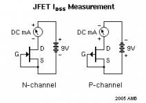
You need to check your input jfets prior to replace mosfet.
That can be done using some rough and ready checks with the JFETS in circuit.
DC check.
If there is a voltage across R1 & R2, Q1 & Q2 are conducting current, the voltages should be approximately equal.
AC check.
Fit a shorting link across the gate-source of Q3 & Q4, set P1 & P2 to mid point resistance, apply a signal to the input and scope the drains of Q1 & Q2 (or measure with a multimeter set for AC volts).
Reset P1 & P2 to minimum resistance before removing the gate-source shorting links.
- Home
- Amplifiers
- Pass Labs
- An illustrated guide to building an F5
