Speaker negatives they are not.
You mean speaker ground or as I prefer to call them speaker Return..
You can locate the Main Audio Ground somewhere between all the other Audio Grounds.
But, not on the smoothing Caps link.
Trying this has been in the queue for a bit longer than I was hoping. Sorry.
Long story made short, Andrew is quite correct -- placing the speaker Negative at the point where the input and the PSU all connect has made it quieter by an order of magnitude.

Even the transformer even has less mechanical hummm.
So, the scheme is -
PSU GND to circuit board GND. Input and speaker negative all attach at that point.
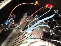
In the photo;
PSU GND (white)
Speaker Negative (black)
Speaker Positive (red)
V+ (green)
V- (blue)
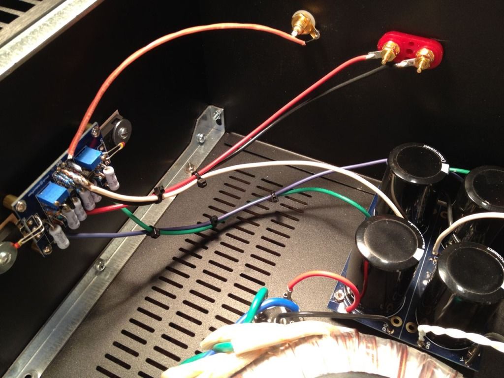
It looks a bit kludgey, but remember that the PCB is quite small (2x3 inches)
Last edited:
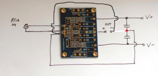
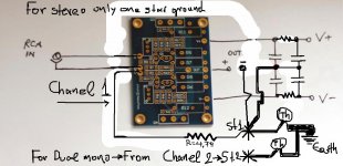
Better solution?
Star ground isolated!
The entire PSU circuit board is isolated from chassis earth via a CL-60 thermistor. It's just not in the photo.
Better solution?
Star ground isolated!
in that illustration, you have star ground on the chassis. so starground directly to earth.
better to have the star ground on the amp boards.
-- placing the speaker [Gnd] at the point where the input and the PSU all connect has made it quieter by an order of magnitude.
Even the transformer even has less mechanical hummm.
So, the scheme is -
PSU GND to circuit board GND. Input and speaker [Gnd] all attach at that point.
6L6,
Thanks for rewiring the Gnd's on your F5
and letting us know the star Gnd node should be on the Amp board.
Pleased to know it worked so well.
.
It does not have to be on the amp board.
Where it must not be is on the PSU where the smoothing caps join together.
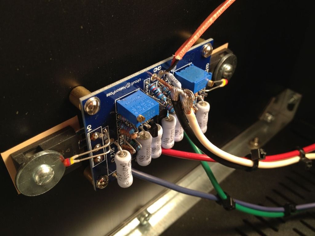
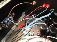
If you look at post 401 you can see two connections on a wire link standing out from the PCB. One from PSU and one from Speaker.
I can't see where the signal screen is connected.
Where it must not be is on the PSU where the smoothing caps join together.
If you look at post 401 you can see two connections on a wire link standing out from the PCB. One from PSU and one from Speaker.
I can't see where the signal screen is connected.
Last edited:
are both the pads GND,
I can't tell by the pic.
Could those two adjacent pads be GND and signal return/ground?
I would expect signal hot and signal return to be adjacent.
Then power ground to be elsewhere.
the pic in post402 & post404 show that the two pads are different, one for power ground and the other (middle pad) for signal ground. The third pad is signal hot.
Last edited:
Ah!
breaks my rule of keeping Sig Gnd separate from Power Gnd.
But with the star ground so close (at the other end of that short wire) the effect is very small. I would still prefer to see sig gnd separate though. That keeps the option to insert a resistor, or to insert a link to maintain the voltage reference from in to out..
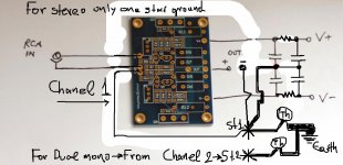
No, the input socket is connected directly to the +IN and -IN pins of the amplifier.
The NFB if any is also connected to the signal -IN pin
The Power Ground is completely separate.
Then one finally references the signal ground to the power ground at the Main Audio Ground. The signal ground connection to this MAG can have a series resistor since it carries virtually no current (I'm talking pA here).
To allow this to happen the sig gnd must be separate from the amp Power Gnd. Many amplifier layouts maintain this separation.
Last edited:
- Home
- Amplifiers
- Pass Labs
- An illustrated guide to building an F5