This thread is a compilation of photos and posts of my F5 build. My original thread became so popular (and chatty) that the photos are spread over many, many pages. To save you the trouble of paging through 500 posts, here it is in one place.
The original, if you are interested -- http://www.diyaudio.com/forums/pass-labs/182723-how-build-f5.html There are lots of neat questions and answers in that thread.
LOTS OF PHOTOS. IT WILL TAKE TIME TO LOAD THE PAGE.
Nothing out of the ordinary, Peter Daniel boards, single transformer, Tech-DIY transistors and other bits, HiFi2000 chassis.
I have collected all the pieces and finally today the chassis arrived from Italy! I am ready to start!
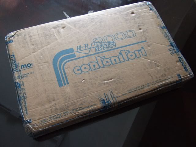
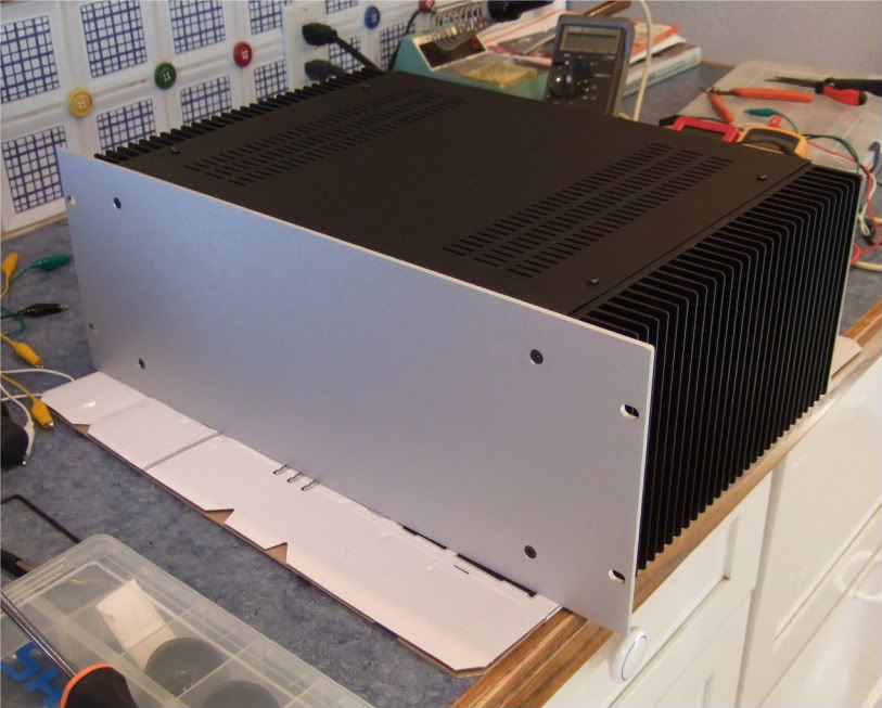
This is From Modushop.biz, it's a "Pesante Dissipante 4U depth 300 mm" (6 1/2" tall x 11 3/4" deep x 19" wide) Which will have a different specific number depending on color and faceplate thickness. I needed to get the shallow(300mm) case, if you have the room for it, you could get the 400mm deep.
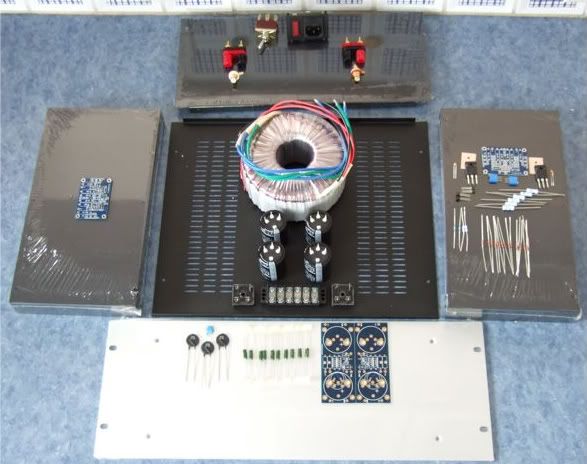
Here is the obligatory "armory" photo. Only one of the amp channels shown.
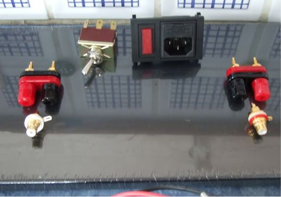
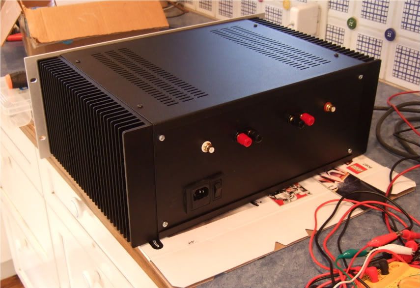
The rear panel. I thought I ordered an Inlet Module with a switch, but I didn't read the datasheet well enough, and it has a neon light power indicator instead. Oh well. Luckily I have a couple of nice bat-handeled switches, I will use one here. The Jacks and RCAs are also from my box, I think they are Vampire.
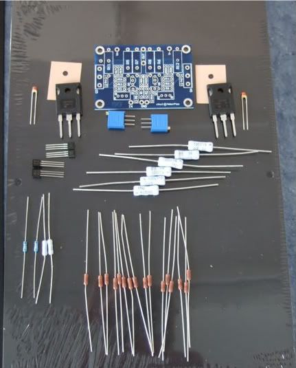
Here are the contents of the Tech-DIY F5 kits, the Peter Daniel's boards, and a couple of silpads.
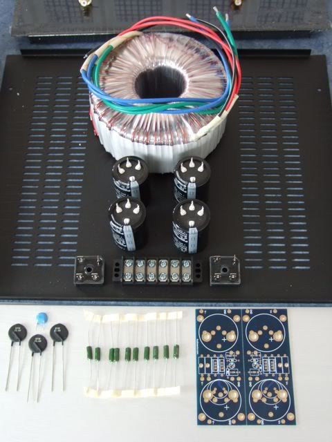
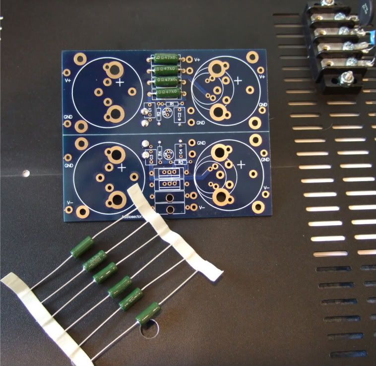
The PSU components. Vishay rectifier blocks, Peter Daniel PSU board, resistors, 33,000uf capacitors, CL-60 thermistors, and a big-honkin' 600VA transformer.
When I was determining the transformer size necessary I must have had a brain-sneeze, I must have only thought of one secondary! Oh well, it was only $20 more than the 'proper' (400VA) size. The 4-pin caps will work on the board with just a bit of modification.
If you were wondering, the Peter Daniel boards are very small. Also very nice!
As mentioned earlier I needed to get a few more things before proceeding with the build…
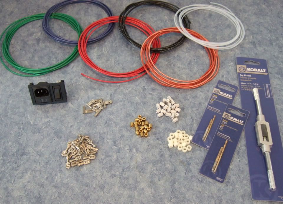
Specifically, wire, connectors, standoffs, spacers, and a tap set. (also a couple of other things not photographed.)
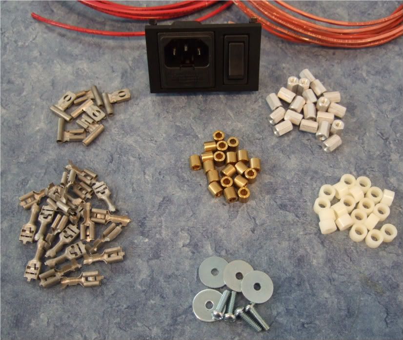
As I am not exactly sure what will be the best standoff/spacer, I bought an assortment. Brass, Nylon, and 'real' 6-32 thread standoffs. Also shown are the 1/4" connector spades, the 6-32 bolts and fender washers for mounting the power transistors.
Also note the Power Inlet module now has a switch!
Not photographed is a big pile of 4-40 hardware for mounting the boards, as well as a few more 6-32 bolts for the rectifier blocks and barrier strip.
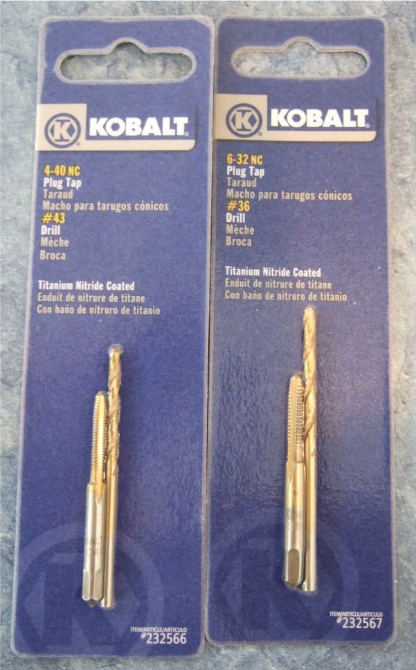
The store I went to didn't have taps without the drill bits, but since they are the exact size for the tap, I didn't see any disadvantage in getting them.
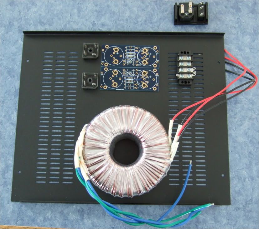
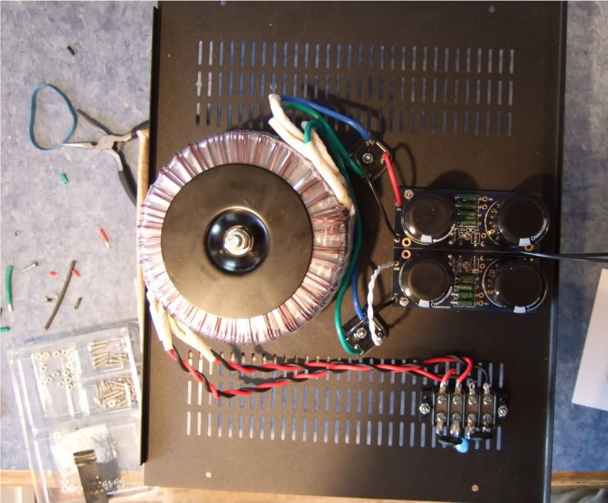
Trying to detemine the best layout for the bottom panel. The Transformer is positioned in the front of the case.
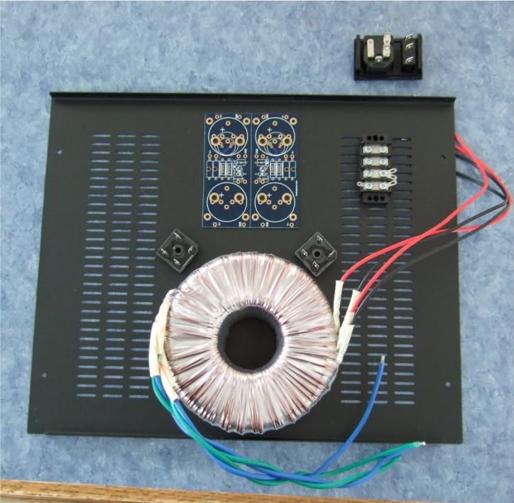
I like this better, it will lead to more symmetrical wiring. Which although not necessary, appeals to me.
If I had the 400mm deep chassis I would also have the power inlet and the barrier strip on the centerline.
I think it is a good idea to leave the chassis vents unobstructed, to keep the heat exchange/airflow as good as possible.
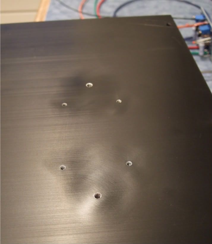
Today I got some drilling done. A lot of effort with not much to look at...
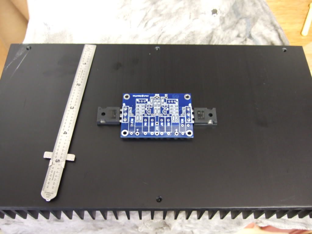
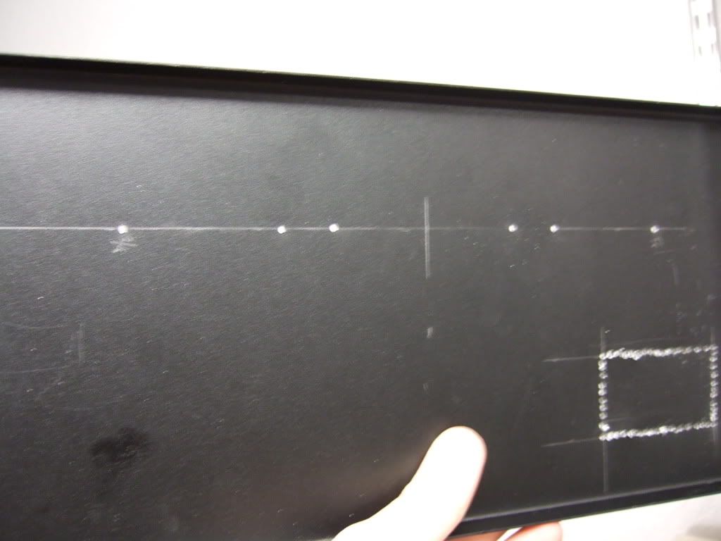
This is the amp board and the 2 power transistors. They will be mounted to the middle of the heatsink.
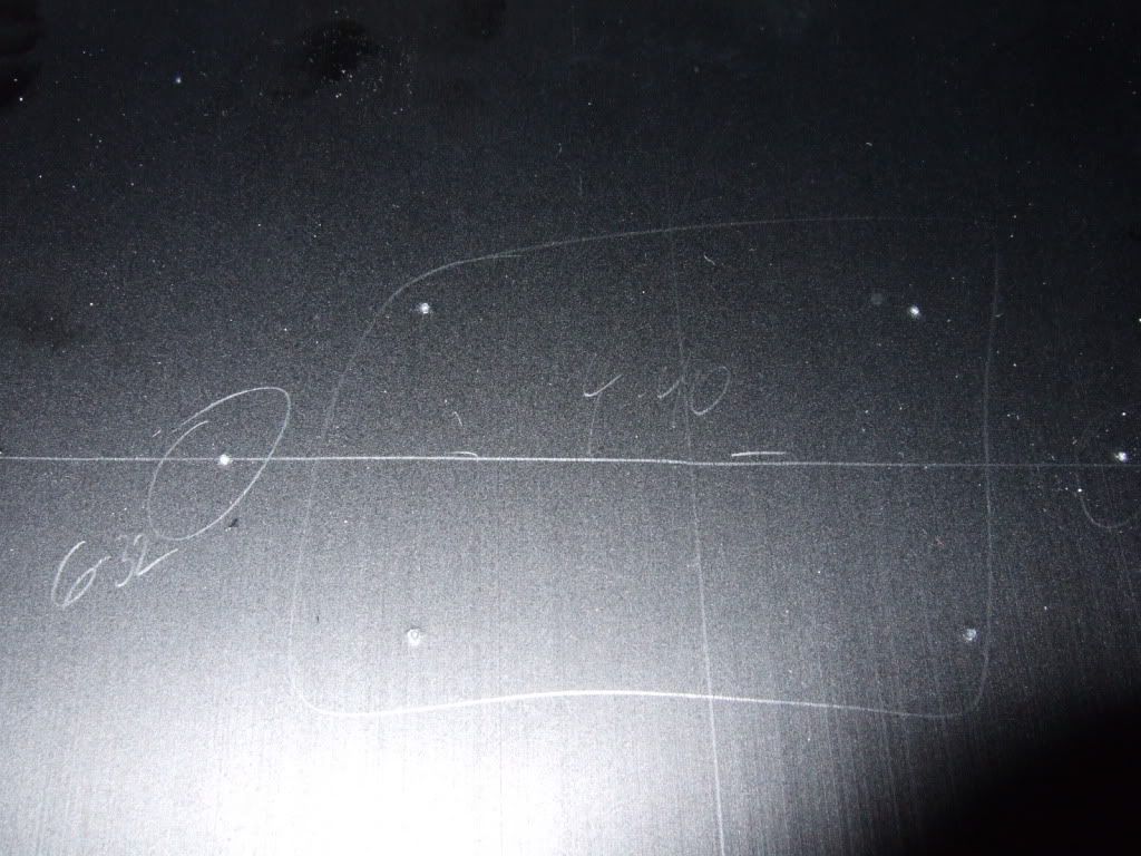
Once the hole locations are marked, I made some starter holes with a set punch. The 4 in the middle will be 4-40, the two on the outside 6-32
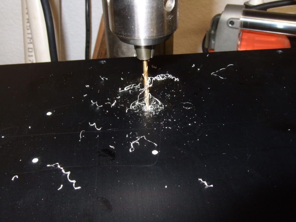
Drilling. Wear safety glasses!
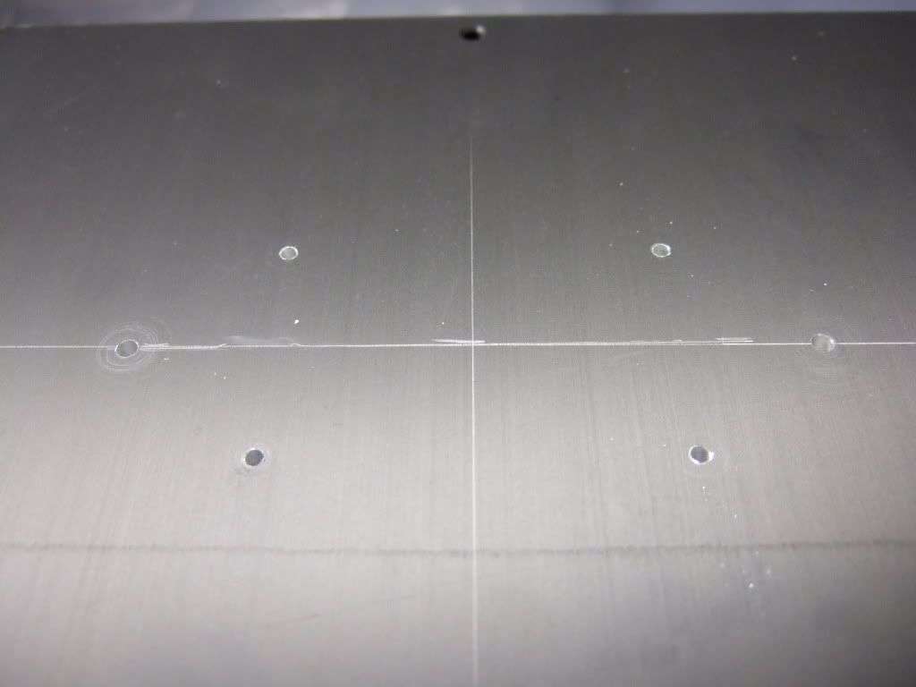
Drilling complete.
My friend was kind enough to tap the holes.
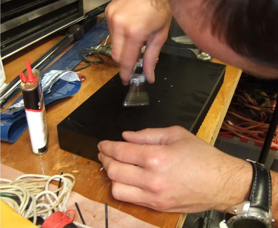
Pilot holes for the RC jacks and Speaker posts. Also the beginning of the IEC inlet module cut-out.
I have all I need in place to build the amplifier circuit and mount it to it's heatsink -
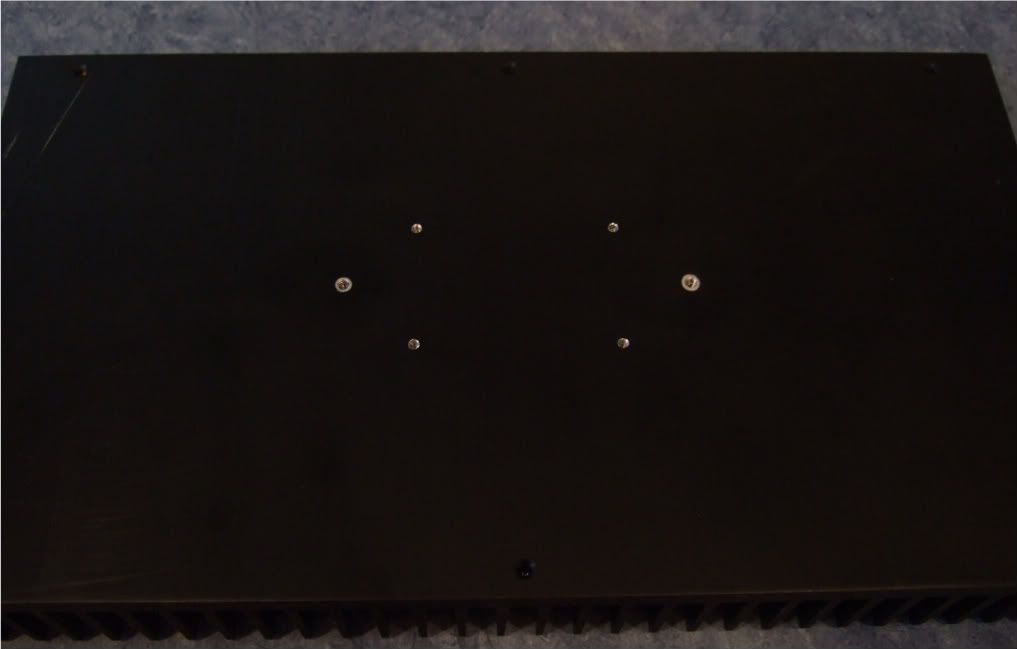
Here is the heatsink, with the holes sanded smooth and cleaned with rubbing alcohol to remove the last oil and sandings/shavings.
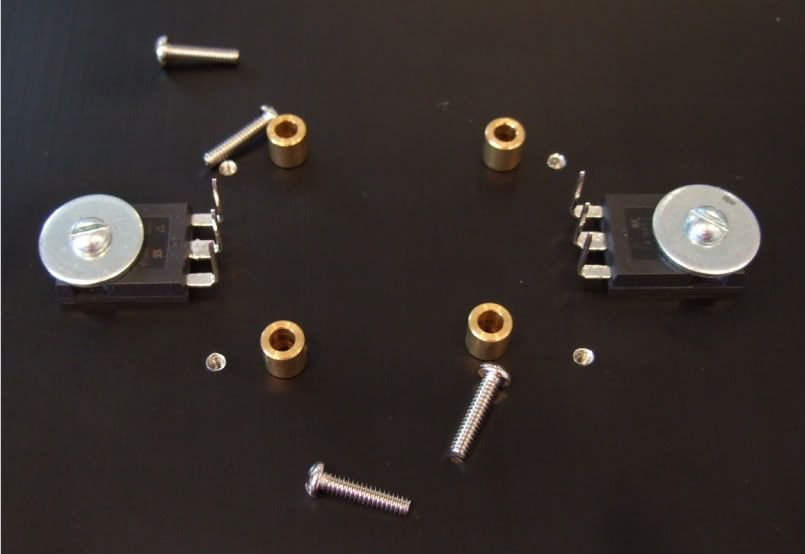
Here is the hardware, 6-32 bolts and fender washers on the transistors, brass spacers and 4-40 bolts on the board
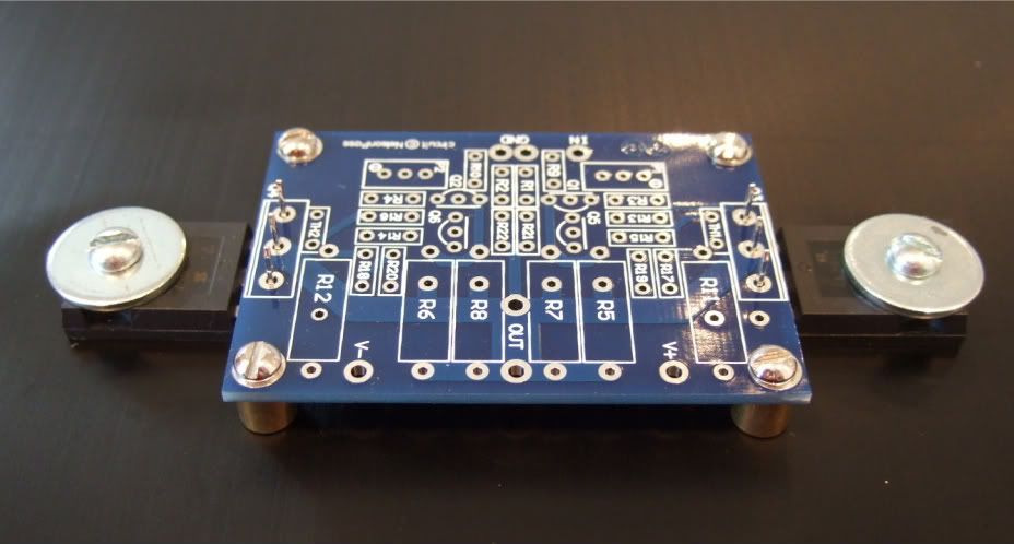
A dry run, to check fit.
Spacing looks good! Now to complete the board...

Stuffing the board. Have your meter at the ready and measure everything before soldering!!! It will save headaches later!!

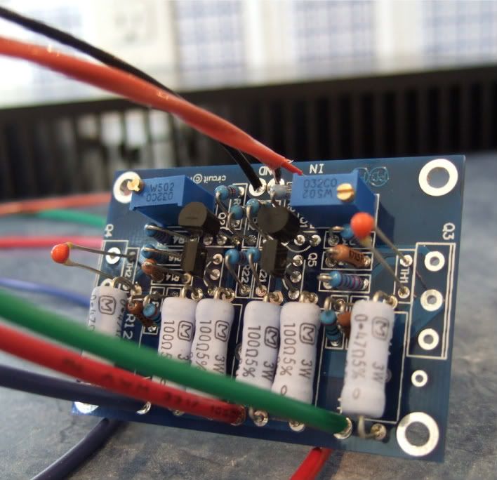
OK, the board is stuffed and the wires attached. My color coding is as follows;
Black - ground
Blue (V-)
Green (V+)
Red (+) out
Red/black twisted pair in orange jacket is input + and -
I like to have the wires much longer than needed to help facilitate neat and tidy wiring later.
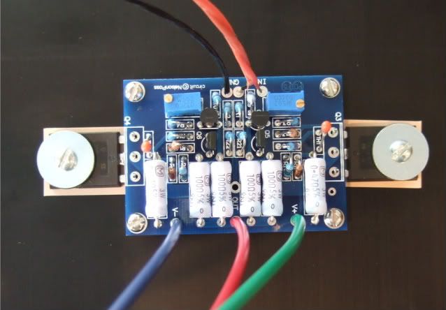
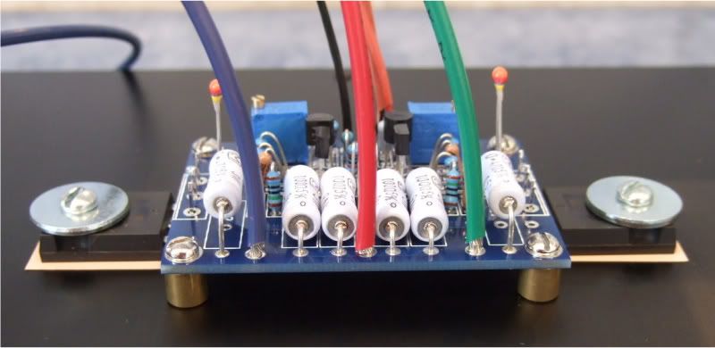
On the heatsink with silpads attached.
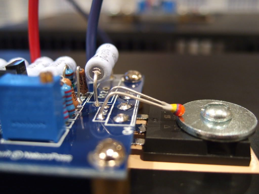
In this photo you can see the following -
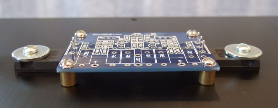
The thermistors are not bent down yet, as I need to get some loctite for the threads before I am actually done... Same with the transistors, they are not soldered and trimmed.
The two 3W resistors on the outside of the PCB (R11 and R12) are standing up off the board so that when it becomes time to set bias, I can easily connect leads across the resistors.
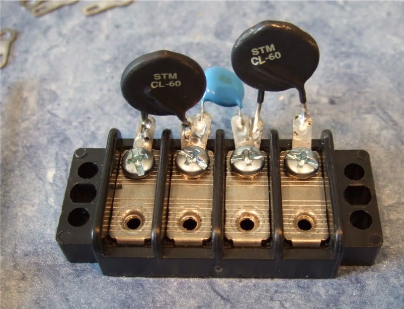
Here is the terminal block showing the thermistors and the capacitor.
Marking the chassis bottom for the PSU board, rectifiers, and (not in photo) the transformer bolt.
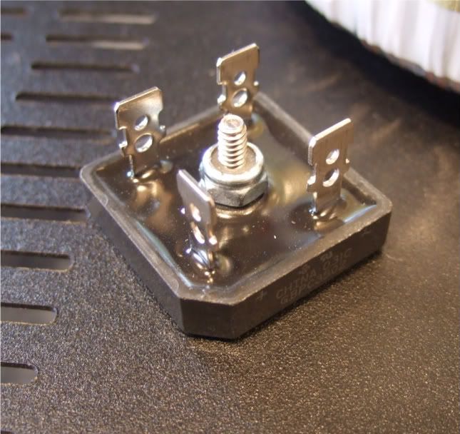
Rectifier block
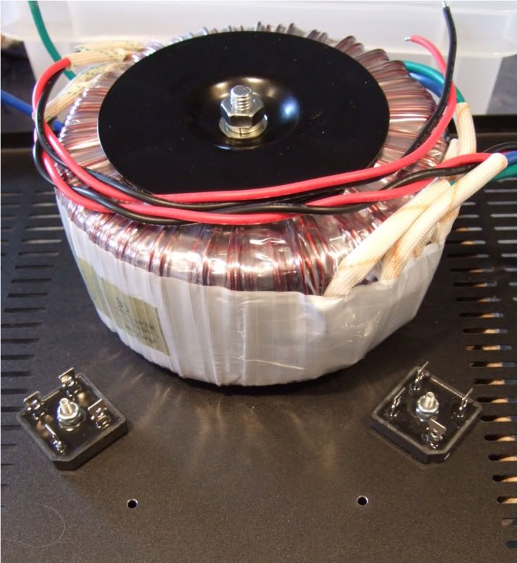
The monster Antek AN-6218
Stuffing the PSU board
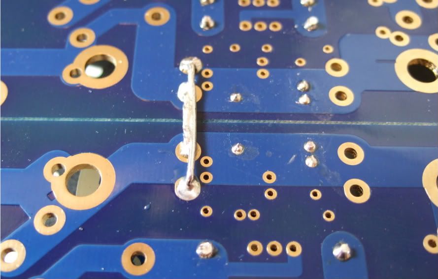
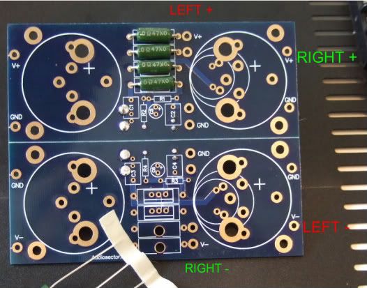
Remember to connect the grounds... Peter Daniel suggests you do it here. I am not sure if you need to have 2 jumpers like I am showing, but a good, low-impedance connection is always a good thing on a powersupply.
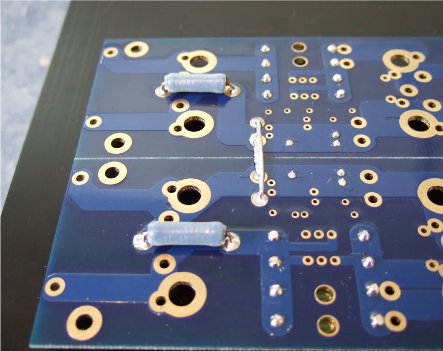
I mounted the bleeder resistors to the bottom of the board. You probably could do it on the top if you had physically smaller caps.
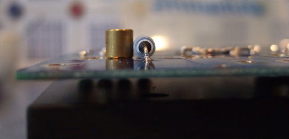
One thing that needs to be checked is if the spacers are taller than the bottom components. Looking good!
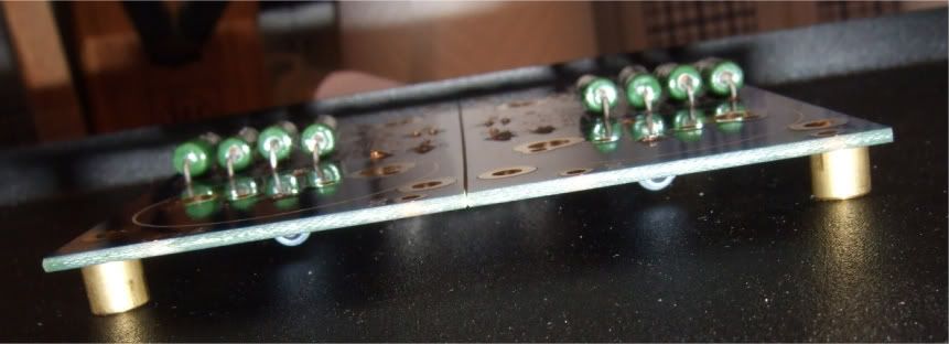
I needed to hold my camera upside-down to get the flash in a place where it could illuminate the bottom. This shows that there is plenty of room under the board.
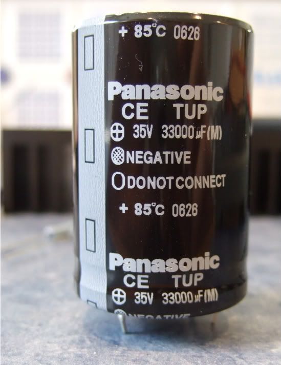
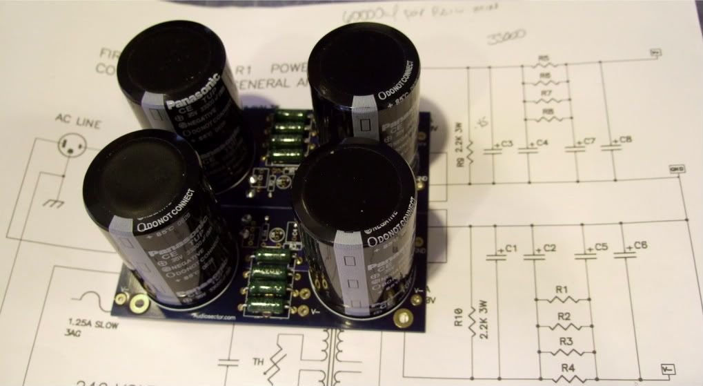
The capacitors I am using.
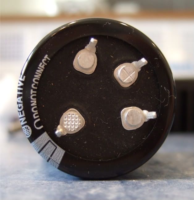
These are a 4-pin cap, and so the unmarked (and unconnected) pins need to be trimmed off.
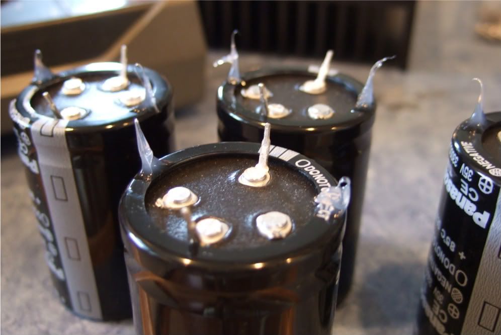
These caps are a bit big to be mounted just by two solder pins, so I am using just a small dab of silicone on the case to help stabilize and support the cans. Also note that the unused pins are now trimmed.
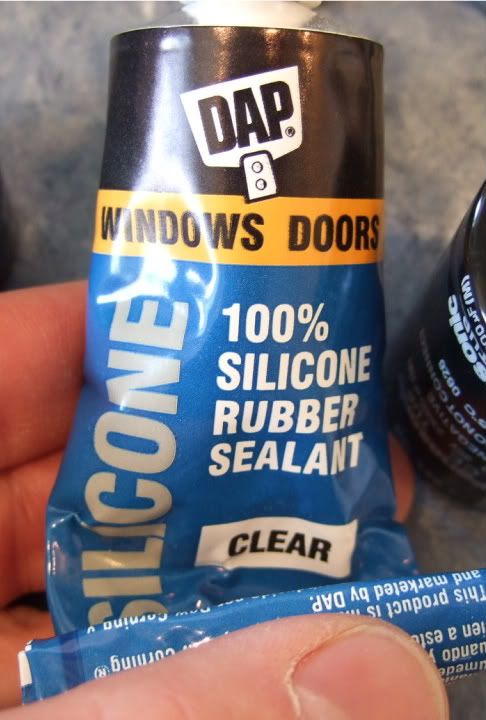
The silicone
The complete (except wires) PSU board.
Wiring the PSU -
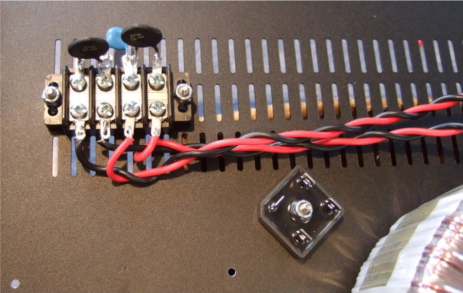
The primaries attached to the barrier strip. AC from the power inlet module will attach to the center two connections of the barrier.
Note the rectifier blocks -- the notched corner is "+" DC, it's opposite is DC "-" The other corners are AC in.
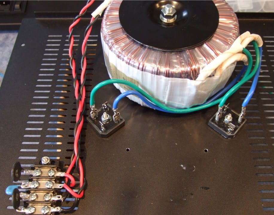
The leads of the secondaries connected to the rectifier blocks. Here you can see the AC connected to the AC in tabs of the rectifiers.
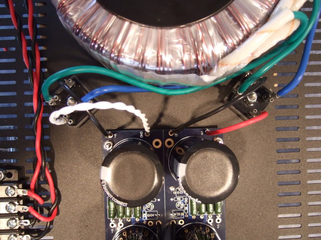
PSU board connected to the rectifiers.
The PSU completed except for AC in. This will be from the power inlet module. The black leads at the center of the PSU board will be the speaker negative connections.
Let's look at the PSU schematic just to make sure everything is OK... Remember that I am wiring it for 120v operation, so the transformer primaries are in parallel. People wiring for 240 with a transformer like this, please ignore.
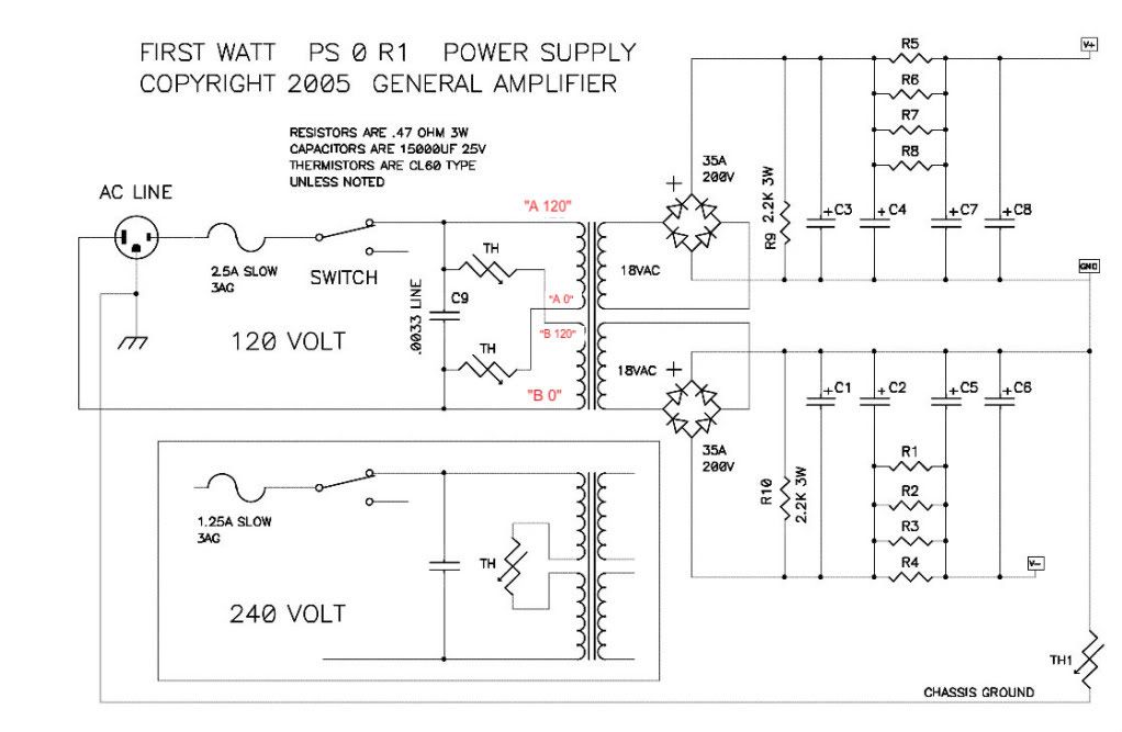
Notes in red are mine.
Look at the connections of the transformer primary, through the thermistors and line cap, to the mains.
Hot AC is connected to the "120" (which in my case is the red leads on the primaries) One red primary is connected to AC hot through a thermistor.
Neutral AC is connected to the black "0" leads, one of which is connected to the AC through a thermistor.
AC Hot and Neutral have a cap across the leads.
So, yes, the AC will be connected to the center 2 posts, which is across the cap.
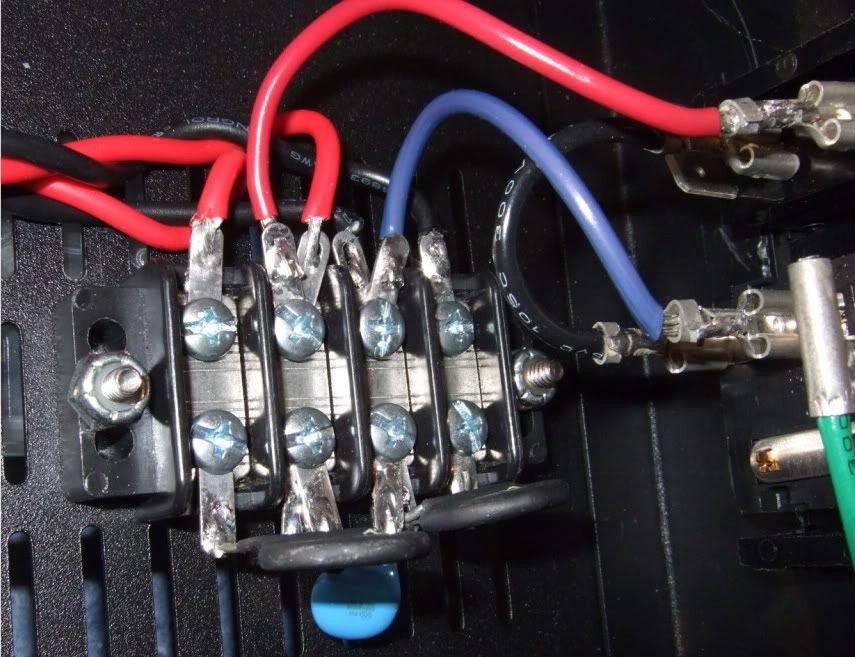
Left to right we have post 1, 2, 3, 4
POST 1 - Transformer primary 'B 0' which will be connected to AC Neutral at post 2, through the thermistor between post 1 and 2.
POST 2 - AC Neutral in (not shown in photo), connected to Transformer primary 'A 0" , a thermistor to post 1, and a line cap to post 3
POST 3 - AC Hot in, connected to transformer primary "B 120", thermistor to post 4, and line cap to post 2
POST 4 - Transformer primary "A 120", connected to AC Hot through the thermistor to post 3
If you look at the red and black wires in the photo you will see that the Mains AC must to pass through a thermistor to connect to each of the 2 primaries. And that is the point of them, to keep inrush under control during powerup.
UPDATE - (This is the only place I can edit this thread) Please look here (post #401 if this thread) for the new, much quieter grounding scheme -- http://www.diyaudio.com/forums/pass-labs/188691-illustrated-guide-building-f5-9.html#post3161231
The original, if you are interested -- http://www.diyaudio.com/forums/pass-labs/182723-how-build-f5.html There are lots of neat questions and answers in that thread.
LOTS OF PHOTOS. IT WILL TAKE TIME TO LOAD THE PAGE.
Nothing out of the ordinary, Peter Daniel boards, single transformer, Tech-DIY transistors and other bits, HiFi2000 chassis.
I have collected all the pieces and finally today the chassis arrived from Italy! I am ready to start!
This is From Modushop.biz, it's a "Pesante Dissipante 4U depth 300 mm" (6 1/2" tall x 11 3/4" deep x 19" wide) Which will have a different specific number depending on color and faceplate thickness. I needed to get the shallow(300mm) case, if you have the room for it, you could get the 400mm deep.
Here is the obligatory "armory" photo. Only one of the amp channels shown.
The rear panel. I thought I ordered an Inlet Module with a switch, but I didn't read the datasheet well enough, and it has a neon light power indicator instead. Oh well. Luckily I have a couple of nice bat-handeled switches, I will use one here. The Jacks and RCAs are also from my box, I think they are Vampire.
Here are the contents of the Tech-DIY F5 kits, the Peter Daniel's boards, and a couple of silpads.
The PSU components. Vishay rectifier blocks, Peter Daniel PSU board, resistors, 33,000uf capacitors, CL-60 thermistors, and a big-honkin' 600VA transformer.
When I was determining the transformer size necessary I must have had a brain-sneeze, I must have only thought of one secondary! Oh well, it was only $20 more than the 'proper' (400VA) size. The 4-pin caps will work on the board with just a bit of modification.
If you were wondering, the Peter Daniel boards are very small. Also very nice!
As mentioned earlier I needed to get a few more things before proceeding with the build…
Specifically, wire, connectors, standoffs, spacers, and a tap set. (also a couple of other things not photographed.)
As I am not exactly sure what will be the best standoff/spacer, I bought an assortment. Brass, Nylon, and 'real' 6-32 thread standoffs. Also shown are the 1/4" connector spades, the 6-32 bolts and fender washers for mounting the power transistors.
Also note the Power Inlet module now has a switch!
Not photographed is a big pile of 4-40 hardware for mounting the boards, as well as a few more 6-32 bolts for the rectifier blocks and barrier strip.
The store I went to didn't have taps without the drill bits, but since they are the exact size for the tap, I didn't see any disadvantage in getting them.
Trying to detemine the best layout for the bottom panel. The Transformer is positioned in the front of the case.
I like this better, it will lead to more symmetrical wiring. Which although not necessary, appeals to me.
If I had the 400mm deep chassis I would also have the power inlet and the barrier strip on the centerline.
I think it is a good idea to leave the chassis vents unobstructed, to keep the heat exchange/airflow as good as possible.
Today I got some drilling done. A lot of effort with not much to look at...
This is the amp board and the 2 power transistors. They will be mounted to the middle of the heatsink.
Once the hole locations are marked, I made some starter holes with a set punch. The 4 in the middle will be 4-40, the two on the outside 6-32
Drilling. Wear safety glasses!
Drilling complete.
My friend was kind enough to tap the holes.
Pilot holes for the RC jacks and Speaker posts. Also the beginning of the IEC inlet module cut-out.
I have all I need in place to build the amplifier circuit and mount it to it's heatsink -
Here is the heatsink, with the holes sanded smooth and cleaned with rubbing alcohol to remove the last oil and sandings/shavings.
Here is the hardware, 6-32 bolts and fender washers on the transistors, brass spacers and 4-40 bolts on the board
A dry run, to check fit.
Spacing looks good! Now to complete the board...
Stuffing the board. Have your meter at the ready and measure everything before soldering!!! It will save headaches later!!
OK, the board is stuffed and the wires attached. My color coding is as follows;
Black - ground
Blue (V-)
Green (V+)
Red (+) out
Red/black twisted pair in orange jacket is input + and -
I like to have the wires much longer than needed to help facilitate neat and tidy wiring later.
On the heatsink with silpads attached.
In this photo you can see the following -
The thermistors are not bent down yet, as I need to get some loctite for the threads before I am actually done... Same with the transistors, they are not soldered and trimmed.
The two 3W resistors on the outside of the PCB (R11 and R12) are standing up off the board so that when it becomes time to set bias, I can easily connect leads across the resistors.
Here is the terminal block showing the thermistors and the capacitor.
Marking the chassis bottom for the PSU board, rectifiers, and (not in photo) the transformer bolt.
Rectifier block
The monster Antek AN-6218
Stuffing the PSU board
Remember to connect the grounds... Peter Daniel suggests you do it here. I am not sure if you need to have 2 jumpers like I am showing, but a good, low-impedance connection is always a good thing on a powersupply.
I mounted the bleeder resistors to the bottom of the board. You probably could do it on the top if you had physically smaller caps.
One thing that needs to be checked is if the spacers are taller than the bottom components. Looking good!
I needed to hold my camera upside-down to get the flash in a place where it could illuminate the bottom. This shows that there is plenty of room under the board.
The capacitors I am using.
These are a 4-pin cap, and so the unmarked (and unconnected) pins need to be trimmed off.
These caps are a bit big to be mounted just by two solder pins, so I am using just a small dab of silicone on the case to help stabilize and support the cans. Also note that the unused pins are now trimmed.
The silicone
The complete (except wires) PSU board.
Wiring the PSU -
The primaries attached to the barrier strip. AC from the power inlet module will attach to the center two connections of the barrier.
Note the rectifier blocks -- the notched corner is "+" DC, it's opposite is DC "-" The other corners are AC in.
The leads of the secondaries connected to the rectifier blocks. Here you can see the AC connected to the AC in tabs of the rectifiers.
PSU board connected to the rectifiers.
The PSU completed except for AC in. This will be from the power inlet module. The black leads at the center of the PSU board will be the speaker negative connections.
Let's look at the PSU schematic just to make sure everything is OK... Remember that I am wiring it for 120v operation, so the transformer primaries are in parallel. People wiring for 240 with a transformer like this, please ignore.
Notes in red are mine.
Look at the connections of the transformer primary, through the thermistors and line cap, to the mains.
Hot AC is connected to the "120" (which in my case is the red leads on the primaries) One red primary is connected to AC hot through a thermistor.
Neutral AC is connected to the black "0" leads, one of which is connected to the AC through a thermistor.
AC Hot and Neutral have a cap across the leads.
So, yes, the AC will be connected to the center 2 posts, which is across the cap.
Left to right we have post 1, 2, 3, 4
POST 1 - Transformer primary 'B 0' which will be connected to AC Neutral at post 2, through the thermistor between post 1 and 2.
POST 2 - AC Neutral in (not shown in photo), connected to Transformer primary 'A 0" , a thermistor to post 1, and a line cap to post 3
POST 3 - AC Hot in, connected to transformer primary "B 120", thermistor to post 4, and line cap to post 2
POST 4 - Transformer primary "A 120", connected to AC Hot through the thermistor to post 3
If you look at the red and black wires in the photo you will see that the Mains AC must to pass through a thermistor to connect to each of the 2 primaries. And that is the point of them, to keep inrush under control during powerup.
UPDATE - (This is the only place I can edit this thread) Please look here (post #401 if this thread) for the new, much quieter grounding scheme -- http://www.diyaudio.com/forums/pass-labs/188691-illustrated-guide-building-f5-9.html#post3161231
Last edited:
More progress! It's actually looking like an amp now... 
The holes in the heatsinks are slightly countersunk and de-burred. I smoothed out the area near the heatsink interface with a foam emery board, it should help thermal conductivity, even if just a little. It may look scratchy in the photo, but it is noticeably smoother to the touch than the stock surface.
The transistors are soldered, the thermistors are bent and touching the washer.
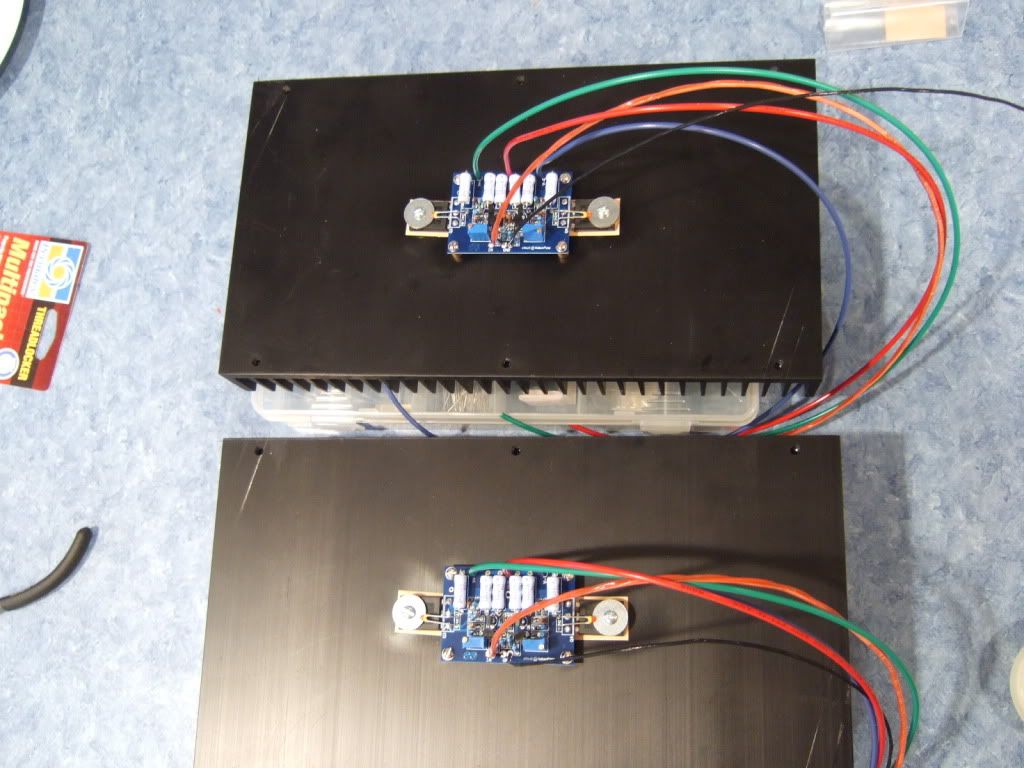
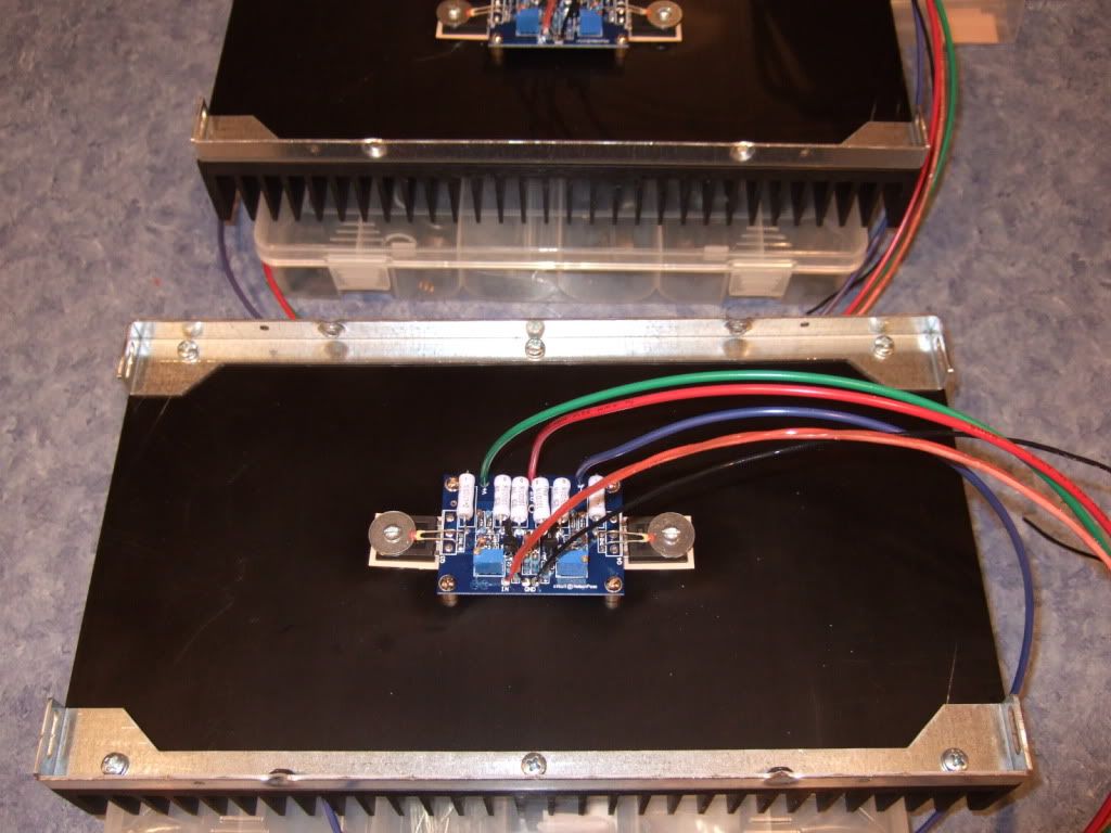
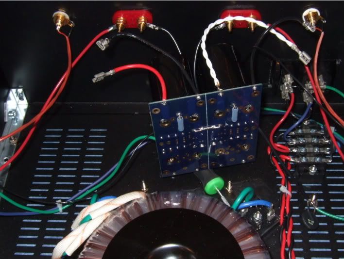
Here is a photo of the final assembly of the 2 amp channels.
These brackets are part of the chassis.
This is the mains connection, from the back of the power inlet module. Red is hot, it is switched and fused. Blue is neutral.
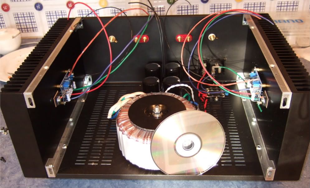
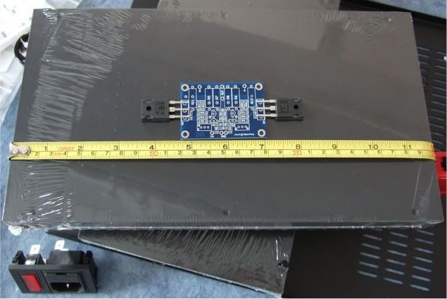
Hey look! It's starting to resemble an amp!
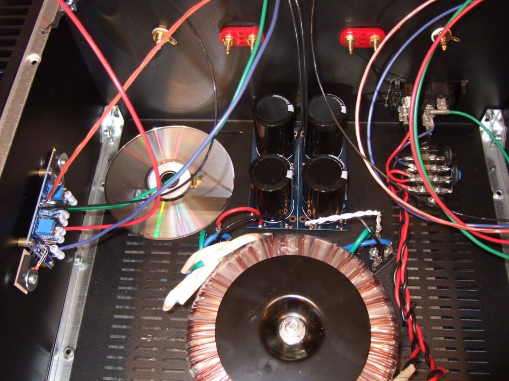
Obviously, the CD is for scale.
This channel is completely wired.
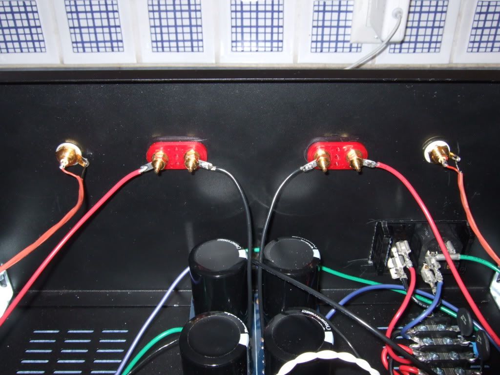
The back panel. Yes, the speaker negatives come from the PSU board.
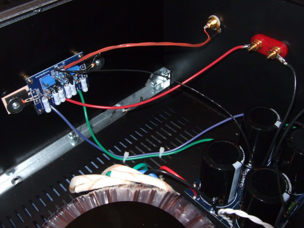
I decided to use existing pads on the PSU board to send power to the amp boards. This is how I connected the V+ and V- wires.
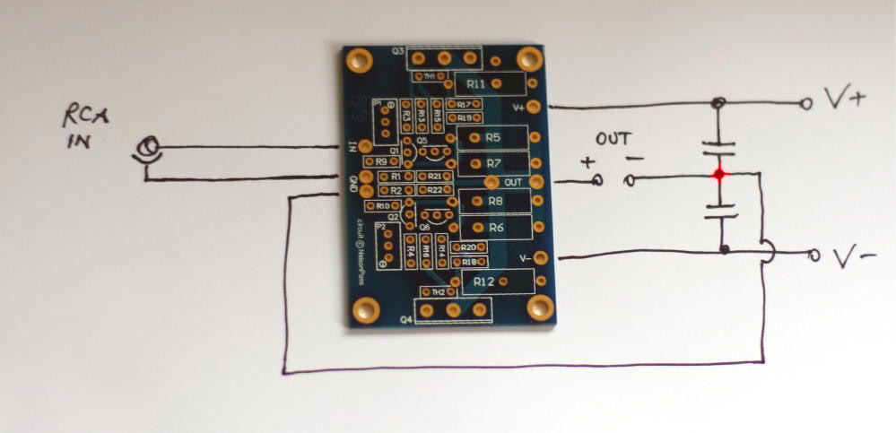
This is the way the PSU board is hooked to the amp board. (Image courtesy of Peter Daniel)
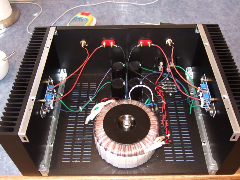
Here is where I left it today -- the left amp channel is wired and finished. The opposite is wired, but needs the wires dressed. The PSU board is complete except for the connection to chassis ground via the last CL-60 thermistor. The AC inlet is also in need of the safety lead connected to chassis ground.
`````````
This is the procedure for firing up the amp and setting the bias. You will refer to it often during the process -
I (CanAmMan) got this info today from Zen Mod regarding "firing up" the F5 and setting the bias. It's the most detailed and informative (and practical) info I've seen on the subject. I wanted to pass it along, as we collectively get close to "turning on the big switch". Great info...!
From Zen Mod:
dial both pots to 0 ohms ( check with ohmmeter )
place one voltmeter across PSU caps ( best between + and - of PSU) to observe max voltage of PSU
place one voltmeter at output - to observe offset
place one voltmeter across one source resistors of output mosfets ; it doesn't matter which one .
for test - slowly dial up Variac ( presuming that you have one , as man with many skills) up to full mains voltage , observing voltage at PSU ....... thinking about max cap voltage ( 25V as in FW ? ) , because with 0 Iq PSU is unloaded and voltage is maxed
if nothing is smelling - leave Variac at full mains ;
what's important - Iq must be very low , offset is irrelevant in this moment .
now turn one pot one turn ( assuming that you have multiturns )
then turn other pot one turn
observe Iq and offset
proceed one then second pot , again just one turn
observe Iq and offset
again one turn + one turn
now you are probably in range when you can see which pot is pulling offset in right direction - to 0 .
proceed iteratively with pots , while you set - say - 75% of desired Iq and zero offset
now - put lid on box and let it cook for a while - until yo get thermal equilibrium on heatsinks
it's best to use wire/clips to leave those voltmeters in place ;
open the lid , up bias to - say - 90% of desired one ,while maintaining offset
put lid on , let it cook
check ;
if all is OK - move voltmeters for Iq and offset to other channel and repeat procedure
use it few days at 90% of desired bias , then check and set to 100%
remember - temp. equilibrium with lid on is important
`````````
There was a little bit of mechanical changes to the chassis necessary before firing it up...
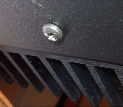
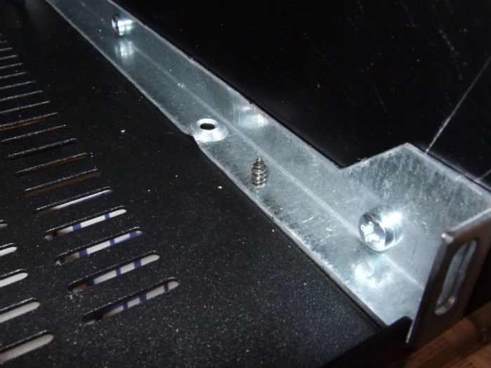
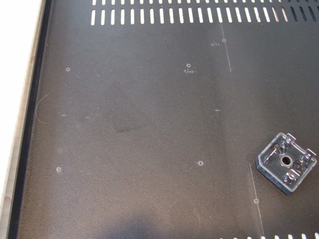
This is a photo of the interface that is supposed to hold the entire bottom plate to the chassis. 4 sheetmetal screws. Really? Who thought this was good idea? Anyway, It needs to be addressed...
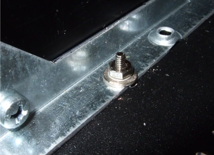
Washers and real hardware to the rescue! This is the new interior hardware,
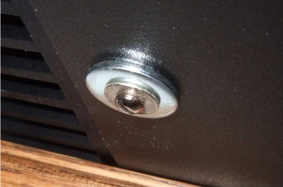
And this is the exterior. I have a bunch of the fender washers, so it seemed like a good place to use one. This should hold the 12lb (5.4kg) transformer and the rest of the PSU securely to the chassis.
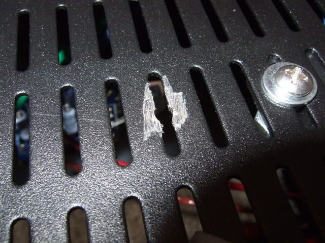
Lastly I needed to make the chassis safety earth. So I scraped the paint (top and bottom) until bare metal was showing, and secure a bolt with star washer also on both sides. This way the star washer digs into the bare metal, making a good connection.
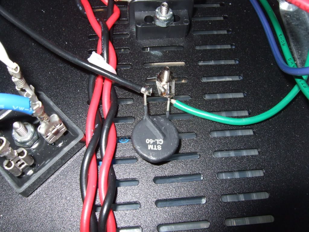
This tab actually has star washer crenellations in it, making it perfect for the application. here you see the safety earth lead (green from the IEC inlet) and the black lead connected through the thermistor to the PSU board. The thermistor does not touch the chassis except for the connection to the ground tab.
It's a bit busy over in that corner, but oh well...
So...
Um...
I'm actually to where I can power it up. I'm a bit apprehensive, as I have never built a solid state device like this before, and SS does not have the latitude that tubes give you. (which is to say, you can hammer tubes with too much current and voltage for a little while with no damage. At least long enough to measure the important things and turn it off...) My understanding is that FETs are not that forgiving...
Well, with a "lightbulb on the hot" mains lead I did in face fire it up, and there was no smoke! Hooray! I had one channel of the amp wired incorrectly, where I connected a V- lead to ground, but it didn't fry anything, and was easy to fix. I was having bias problems, and needed to get a 3rd meter to help see all the relationships during the process. The threads picked back up here…
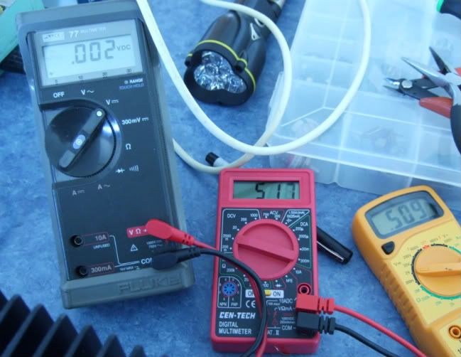
I got to the store and bought a 3rd meter. (And a 4th, as they were 5 bucks each...) Yes, they are not that good, but they are good enough for what I need.
As fas as I can tell, I don't have enough bias range, and need to change the resistor in parallel with the pots... But I could be totally wrong...
With 0 offset, I can only bias to .15v
With .6 bias, the offset is .3v !!
(somebody suggested that the values of R3 and R4 might be too low for my specific FETs. So…)
Update -
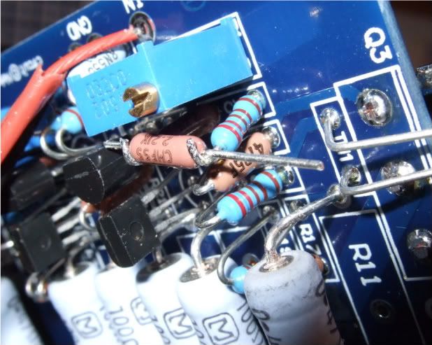
I have a number of 2.2k resistors in my box, so I installed another in series with R3 and R4, (Which are the resistors in parallel with the pots) bringing the total resistance to about 4.5k
I have this complete on one channel, it has biased up properly (cold) It is currently heating up. I will check it in a half an hour and see how it's going.
(It was going OK, but not great)
One channel (the first to get the resistors changed) is biasing well. .6v bias and 0 offset. I had to bias it to about .55 when cold, and when warming up it settled into perfect.
The other channel has the same resistors changed, but I'm still running out of range on the potentiometers... It's awfully close, .51v and 5mv offset, but that's all it's got. Cold it wouldn't go past .4v or so.
Should I increase the value of the parallel resistor again on the one channel? It would be easiest to add another 2.2k or thereabouts in series with the other 2 resistors, as that would keep from having to de-solder something from the PCB.
(ZenMod jumped in with the answer…)
"so - now you know recipe - increase them further
seems that :
1 . Idss of used Jfets is small ,or
2. Ugs of used mosfets is unusually big , or
3 . both 1 & 2"
Awesome! Now I know how to fix it! I added another 2.2k resistor in series on the channel that didn't bias fully, (Bring the total up to 6.6k!) and long story made short, it looks good!!
The amp is currently warming up as I type this, I am fully confident that it will be fine and thermally stable. Back to photos… (which might seem a bit out of order, but will make sense by the end.)
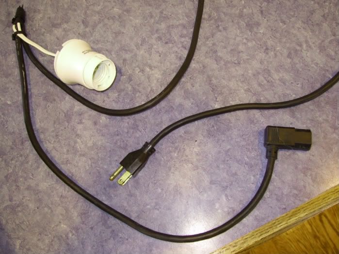
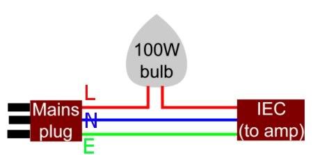
The powercord with series lightbulb. Although everything was ok, I'm glad that now I have this in my toolbox. Wiring is shown below. Use an incandescent lightbulb.
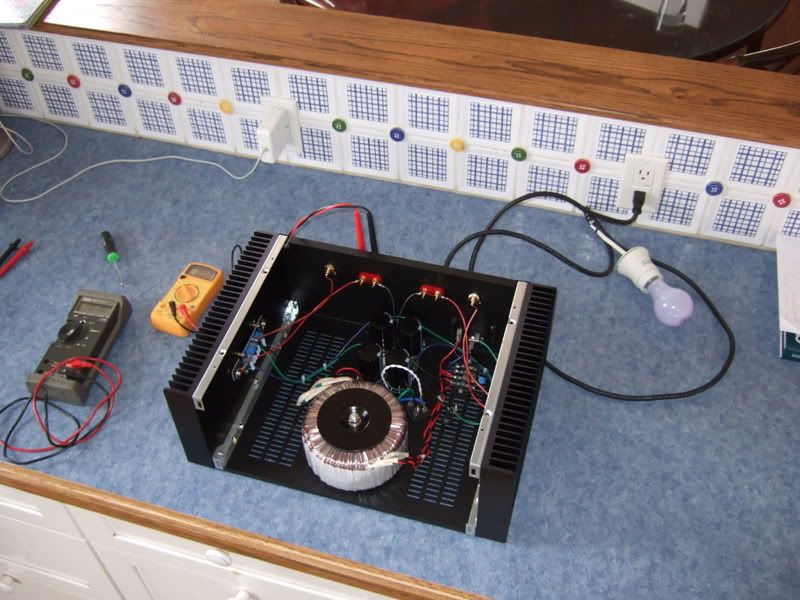
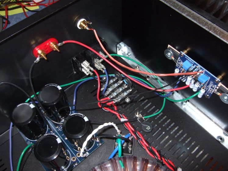
This is the photo taken before flipping the switch the first time... just in case something blows up...
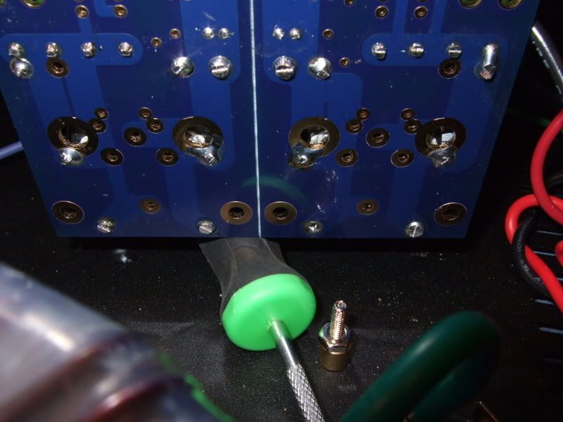
Previously I mentioned that one channel was not connected properly to the PSU, the wire on the pad just to the right of the screwdriver needed to be moved further to the right.
I am extremely happy that I chose to use spades connecting the wires to the rectifiers - without that, it would have been extremely difficult to get the board back up where it could be soldered.
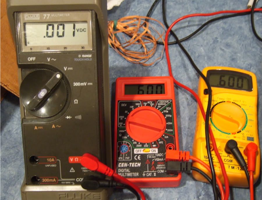
WhooHoo!!!!! YeeHah! This is going great! Sure, I am pretty much at the end of the potentiometer's adjustment, but look at those numbers! Let's go to the other side and make it look the same...
...
... And the results are nothing short of disaster. It's so bad that I don't even take a photo. The other channel is will not bias to more than .2v with zero offset, and the most bias I can get is only .45v or so, and that's with .4v offset! Ugh.
So the question is posed to the Gurus, and they say to increase the value of resistor paralleled with the pot. (R3, R4)
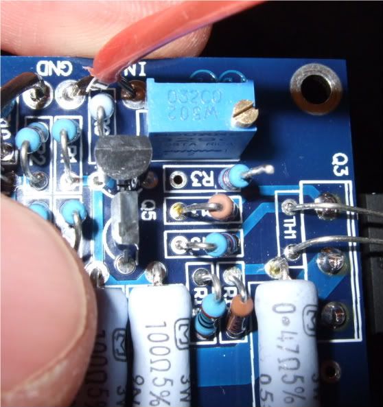
So out comes one lead,
And in goes another resistor.
Twist
Solder and trim. Easy! (Well, desoldering something off a PCB is never fun, but no damage was done to the board. Whew!)
Ok! Let's look at the numbers!
Hmmm... That's it? .5v?? And this is at the end of the range of adjustment of the pot...
Well, the good news is that I did the resistor mod to both channels, and the 'good' one still biased up nicely, now with lots of adjustment left in the pot.
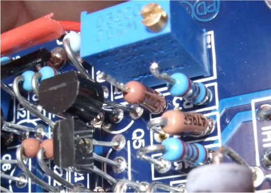
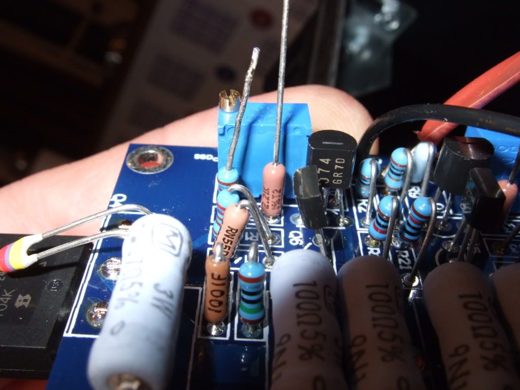
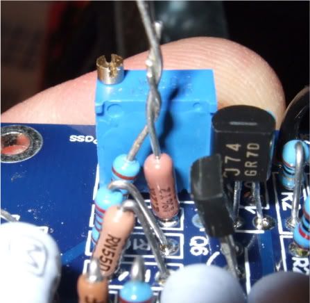
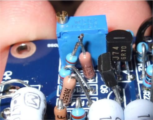
This time I really do not want to solder the board again (and risk lifting a trace), so I'm going to cheat and add another resistor to the ones already there. So the recently twisted leads are de-soldered and un-twisted...
And another added...
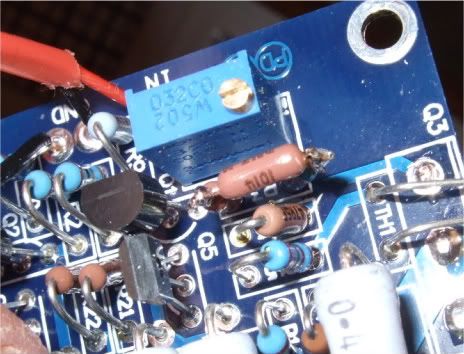
And trimmed. Yes, it's not that pretty. Oh well.
...But it biases up beautifully! Hooray!!
Here it is, al buttoned up and complete -
The holes in the heatsinks are slightly countersunk and de-burred. I smoothed out the area near the heatsink interface with a foam emery board, it should help thermal conductivity, even if just a little. It may look scratchy in the photo, but it is noticeably smoother to the touch than the stock surface.
The transistors are soldered, the thermistors are bent and touching the washer.
Here is a photo of the final assembly of the 2 amp channels.
These brackets are part of the chassis.
This is the mains connection, from the back of the power inlet module. Red is hot, it is switched and fused. Blue is neutral.
Hey look! It's starting to resemble an amp!
Obviously, the CD is for scale.
This channel is completely wired.
The back panel. Yes, the speaker negatives come from the PSU board.
I decided to use existing pads on the PSU board to send power to the amp boards. This is how I connected the V+ and V- wires.
This is the way the PSU board is hooked to the amp board. (Image courtesy of Peter Daniel)
Here is where I left it today -- the left amp channel is wired and finished. The opposite is wired, but needs the wires dressed. The PSU board is complete except for the connection to chassis ground via the last CL-60 thermistor. The AC inlet is also in need of the safety lead connected to chassis ground.
`````````
This is the procedure for firing up the amp and setting the bias. You will refer to it often during the process -
I (CanAmMan) got this info today from Zen Mod regarding "firing up" the F5 and setting the bias. It's the most detailed and informative (and practical) info I've seen on the subject. I wanted to pass it along, as we collectively get close to "turning on the big switch". Great info...!
From Zen Mod:
dial both pots to 0 ohms ( check with ohmmeter )
place one voltmeter across PSU caps ( best between + and - of PSU) to observe max voltage of PSU
place one voltmeter at output - to observe offset
place one voltmeter across one source resistors of output mosfets ; it doesn't matter which one .
for test - slowly dial up Variac ( presuming that you have one , as man with many skills) up to full mains voltage , observing voltage at PSU ....... thinking about max cap voltage ( 25V as in FW ? ) , because with 0 Iq PSU is unloaded and voltage is maxed
if nothing is smelling - leave Variac at full mains ;
what's important - Iq must be very low , offset is irrelevant in this moment .
now turn one pot one turn ( assuming that you have multiturns )
then turn other pot one turn
observe Iq and offset
proceed one then second pot , again just one turn
observe Iq and offset
again one turn + one turn
now you are probably in range when you can see which pot is pulling offset in right direction - to 0 .
proceed iteratively with pots , while you set - say - 75% of desired Iq and zero offset
now - put lid on box and let it cook for a while - until yo get thermal equilibrium on heatsinks
it's best to use wire/clips to leave those voltmeters in place ;
open the lid , up bias to - say - 90% of desired one ,while maintaining offset
put lid on , let it cook
check ;
if all is OK - move voltmeters for Iq and offset to other channel and repeat procedure
use it few days at 90% of desired bias , then check and set to 100%
remember - temp. equilibrium with lid on is important
`````````
There was a little bit of mechanical changes to the chassis necessary before firing it up...
This is a photo of the interface that is supposed to hold the entire bottom plate to the chassis. 4 sheetmetal screws. Really? Who thought this was good idea? Anyway, It needs to be addressed...
Washers and real hardware to the rescue! This is the new interior hardware,
And this is the exterior. I have a bunch of the fender washers, so it seemed like a good place to use one. This should hold the 12lb (5.4kg) transformer and the rest of the PSU securely to the chassis.
Lastly I needed to make the chassis safety earth. So I scraped the paint (top and bottom) until bare metal was showing, and secure a bolt with star washer also on both sides. This way the star washer digs into the bare metal, making a good connection.
This tab actually has star washer crenellations in it, making it perfect for the application. here you see the safety earth lead (green from the IEC inlet) and the black lead connected through the thermistor to the PSU board. The thermistor does not touch the chassis except for the connection to the ground tab.
It's a bit busy over in that corner, but oh well...
So...
Um...
I'm actually to where I can power it up. I'm a bit apprehensive, as I have never built a solid state device like this before, and SS does not have the latitude that tubes give you. (which is to say, you can hammer tubes with too much current and voltage for a little while with no damage. At least long enough to measure the important things and turn it off...) My understanding is that FETs are not that forgiving...
Well, with a "lightbulb on the hot" mains lead I did in face fire it up, and there was no smoke! Hooray! I had one channel of the amp wired incorrectly, where I connected a V- lead to ground, but it didn't fry anything, and was easy to fix. I was having bias problems, and needed to get a 3rd meter to help see all the relationships during the process. The threads picked back up here…
I got to the store and bought a 3rd meter. (And a 4th, as they were 5 bucks each...) Yes, they are not that good, but they are good enough for what I need.
As fas as I can tell, I don't have enough bias range, and need to change the resistor in parallel with the pots... But I could be totally wrong...
With 0 offset, I can only bias to .15v
With .6 bias, the offset is .3v !!
(somebody suggested that the values of R3 and R4 might be too low for my specific FETs. So…)
Update -
I have a number of 2.2k resistors in my box, so I installed another in series with R3 and R4, (Which are the resistors in parallel with the pots) bringing the total resistance to about 4.5k
I have this complete on one channel, it has biased up properly (cold) It is currently heating up. I will check it in a half an hour and see how it's going.
(It was going OK, but not great)
One channel (the first to get the resistors changed) is biasing well. .6v bias and 0 offset. I had to bias it to about .55 when cold, and when warming up it settled into perfect.
The other channel has the same resistors changed, but I'm still running out of range on the potentiometers... It's awfully close, .51v and 5mv offset, but that's all it's got. Cold it wouldn't go past .4v or so.
Should I increase the value of the parallel resistor again on the one channel? It would be easiest to add another 2.2k or thereabouts in series with the other 2 resistors, as that would keep from having to de-solder something from the PCB.
(ZenMod jumped in with the answer…)
"so - now you know recipe - increase them further
seems that :
1 . Idss of used Jfets is small ,or
2. Ugs of used mosfets is unusually big , or
3 . both 1 & 2"
Awesome! Now I know how to fix it! I added another 2.2k resistor in series on the channel that didn't bias fully, (Bring the total up to 6.6k!) and long story made short, it looks good!!
The amp is currently warming up as I type this, I am fully confident that it will be fine and thermally stable. Back to photos… (which might seem a bit out of order, but will make sense by the end.)
The powercord with series lightbulb. Although everything was ok, I'm glad that now I have this in my toolbox. Wiring is shown below. Use an incandescent lightbulb.
This is the photo taken before flipping the switch the first time... just in case something blows up...
Previously I mentioned that one channel was not connected properly to the PSU, the wire on the pad just to the right of the screwdriver needed to be moved further to the right.
I am extremely happy that I chose to use spades connecting the wires to the rectifiers - without that, it would have been extremely difficult to get the board back up where it could be soldered.
WhooHoo!!!!! YeeHah! This is going great! Sure, I am pretty much at the end of the potentiometer's adjustment, but look at those numbers! Let's go to the other side and make it look the same...
...
... And the results are nothing short of disaster. It's so bad that I don't even take a photo. The other channel is will not bias to more than .2v with zero offset, and the most bias I can get is only .45v or so, and that's with .4v offset! Ugh.
So the question is posed to the Gurus, and they say to increase the value of resistor paralleled with the pot. (R3, R4)
So out comes one lead,
And in goes another resistor.
Twist
Solder and trim. Easy! (Well, desoldering something off a PCB is never fun, but no damage was done to the board. Whew!)
Ok! Let's look at the numbers!
Hmmm... That's it? .5v?? And this is at the end of the range of adjustment of the pot...
Well, the good news is that I did the resistor mod to both channels, and the 'good' one still biased up nicely, now with lots of adjustment left in the pot.
This time I really do not want to solder the board again (and risk lifting a trace), so I'm going to cheat and add another resistor to the ones already there. So the recently twisted leads are de-soldered and un-twisted...
And another added...
And trimmed. Yes, it's not that pretty. Oh well.
...But it biases up beautifully! Hooray!!
Here it is, al buttoned up and complete -
Last edited:

Hmm, does the power supply board need to be grounded? I'm only asking because, I mistakenly bought nylon standoffs.
nope
nylon washers are good
you need to connect audio gnd to chassis - via NTC
but you already have that on PSU schematic
Glad you posted this, the resistor that is parallel to the pot is confusing me. I have heard several who are using the Toshiba mosfets were having to modify the resistor, but I thought they lowered the resistor to 1.5 or so. Obviously, this is not the case in your build, clear enough.
What output mosfets did you use, and does anyone else have anything to add concerning modifying these resistors? My current build, (F-5 #2,) is using the Toshiba output mosfets. One fellow builder had his fire up fine with standard parts, others seem to have to modify....Any words from anyone on their resistor modification/alteration on their builds?
Russellc
popping fuses
Ok, I've figured out what is happening. I must have been looking at the f5 service guide when I put together the PSU board. CViller's power supply boards labels are not in sync with that schematic.
So the correct value should be 2.2k ohm across the input of (T1 & T2) & (T3 + T4) and not .47kohms.
That's what has been popping my fuse. Silly me. I'll have to swap them around.
I've measured about ~15v dc & ~ 19v dc from the outputs of the bridges. Does that sound about right?

Best to keep this build thread "hijack free"....
6L6.... Jim.... Clear, concise, succinct of your F5 build. Great pics, too. Hopefully, no one will hijack your thread! (Can you get it "locked up"?)
Ooohhhh, Merlin--congrats on being the first and quickest to hijack this fine thread. Perhaps you ought to consider posting your own thread, on your build and problems. And yeah....the 2.2k ohm resistor is a BLEEDER resistor (there for your safety). In any case, where did you find a requirement for .47kohm (470 ohm) resistors in the power supply? They are not part of the design.... (If you want to answer, best to do in a new thread, or one of your existing ones).
6L6.... Jim.... Clear, concise, succinct of your F5 build. Great pics, too. Hopefully, no one will hijack your thread! (Can you get it "locked up"?)
Ok, I've figured out what is happening. I must have been looking at the f5 service guide when I put together the PSU board. CViller's power supply boards labels are not in sync with that schematic.
So the correct value should be 2.2k ohm across the input of (T1 & T2) & (T3 + T4) and not .47kohms.
That's what has been popping my fuse. Silly me. I'll have to swap them around.
I've measured about ~15v dc & ~ 19v dc from the outputs of the bridges. Does that sound about right?
Ooohhhh, Merlin--congrats on being the first and quickest to hijack this fine thread. Perhaps you ought to consider posting your own thread, on your build and problems. And yeah....the 2.2k ohm resistor is a BLEEDER resistor (there for your safety). In any case, where did you find a requirement for .47kohm (470 ohm) resistors in the power supply? They are not part of the design.... (If you want to answer, best to do in a new thread, or one of your existing ones).
CanAmMan said:Hopefully, no one will hijack your thread! (Can you get it "locked up"?)
It doesn't matter. All the photos are in the top posts. What happens past that is gravy.
- Home
- Amplifiers
- Pass Labs
- An illustrated guide to building an F5