Regarding resistance measurements of Mosfet pins to ground, the pins are Gate Drain Source in that order. The middle pin is Drain, and case metal backing is also connected to the Drain. So if it is the middle pin that is measuring .048 (I assume that is Ohms and OL refers to open circuit or infinite resistance), that means your right channel Mosfets have a puncture in the insulating pad between the Mosfets and heatsink. So you have a short circuit to ground at both Mosfet drains, causing the light bulb to stay on.
Your left channel measures fine in that regard.
So you need to replace the right channel insulating pads.
This resistance measurement checks for short to the heatsink and ground due to faulty insulating pad.
To check the Mosfets for damage, you need to desolder them and then do the Mosfet test.
Voltage measurements across R7 and R8 resistors would indicate the current that is flowing through the Mosfets (I=V/0.47). However I am not sure what your OL measurement means. Did you have your meter on VDC? If current is flowing from the power supply through the resistor and then to the Mosfet and exiting from the back of the Mosfet into the heatsink and ground, I would expect a voltage reading across R7 and R8.
Since you have to remove the board to replace the insulating pads, remove the Mosfets and test them to be sure. If you have spares on hand, it may be best to replace them. If you don't have spares, then test them. Or you can take the chance that they are OK and that the only issue is with the insulating pads. However, every time you attach and remove the Mosfets from the heatsink you run the risk of damaging the insulating pads.
Pass DIY Addict
Joined 2000
Paid Member
A better insulating pad is Ceramic aluminum oxide. It transfers heat better than keratherm and wont puncture like all of the flexible pads can.
Thanks Eric, do you have a link for these?
Pass DIY Addict
Joined 2000
Paid Member
Here you go Mark:
Avid 4180G
They are $0.70 each when you buy 25 of them.
You can get 50 of them for $20 on ebay...
Don't forget to use thermal paste with these!
Avid 4180G
They are $0.70 each when you buy 25 of them.
You can get 50 of them for $20 on ebay...
Don't forget to use thermal paste with these!
Last edited:
Here you go Mark:
Avid 4180G
They are $0.70 each when you buy 25 of them.
You can get 50 of them for $20 on ebay...
Don't forget to use thermal paste with these!
Thanks, I'm currently using these: http://tds.loctite.com/tds5/Studio/ShowPDF/BERGQUIST%20SIL%20PAD%20TSP%201600S-EN?pid=BERGQUIST%20SIL%20PAD%20TSP%201600S&format=MTR&subformat=HYS&language=EN&plant=WERCS
I may get the ceramic ones and see if I get an increase in heatsink temp or a faster increase in temp.
Pass DIY Addict
Joined 2000
Paid Member
Mark - I've used a number of Bergquist products and find them to be excellent at thermal transfer and great for initial builds (no messy goop), provided you don't have any raised burs from drilling/tapping holes or microscopic metal slivers that pierce them. As I've also spent time tracing down problems over the years, though, I find them troublesome to work with. They are not repositionable, so once you dismount a transistor, you need to replace them. Piercing is the main problem that I have - especially when extracting a screw that carries out that tiny metal sliver left over from when you tapped the hole years ago. Now you have a new problem on top of the original problem you are trying to track down.
The ceramic ones are nice and rigid. They won't pierce, I haven't yet cracked one, and with some thermal paste, they transfer heat better than any sil-pad type of product that I've tried.
The ceramic ones are nice and rigid. They won't pierce, I haven't yet cracked one, and with some thermal paste, they transfer heat better than any sil-pad type of product that I've tried.
Regarding resistance measurements of Mosfet pins to ground, the pins are Gate Drain Source in that order. The middle pin is Drain, and case metal backing is also connected to the Drain. So if it is the middle pin that is measuring .048 (I assume that is Ohms and OL refers to open circuit or infinite resistance), that means your right channel Mosfets have a puncture in the insulating pad between the Mosfets and heatsink. So you have a short circuit to ground at both Mosfet drains, causing the light bulb to stay on.
Your left channel measures fine in that regard.
So you need to replace the right channel insulating pads.
This resistance measurement checks for short to the heatsink and ground due to faulty insulating pad.
To check the Mosfets for damage, you need to desolder them and then do the Mosfet test.
Voltage measurements across R7 and R8 resistors would indicate the current that is flowing through the Mosfets (I=V/0.47). However I am not sure what your OL measurement means. Did you have your meter on VDC? If current is flowing from the power supply through the resistor and then to the Mosfet and exiting from the back of the Mosfet into the heatsink and ground, I would expect a voltage reading across R7 and R8.
Since you have to remove the board to replace the insulating pads, remove the Mosfets and test them to be sure. If you have spares on hand, it may be best to replace them. If you don't have spares, then test them. Or you can take the chance that they are OK and that the only issue is with the insulating pads. However, every time you attach and remove the Mosfets from the heatsink you run the risk of damaging the insulating pads.
Well for those who are keeping score, I'm now 0 for 2. I tested the left channel and the dim bulb didn't dim. I got OL for a reading on R7 and -579.8 mV on the speaker out.
Taking the channels out to replace the MOSFETs and Keratherm insulators.
I'm not afraid to ask a dumb question, so here it goes... I'm just curious if testing the boards without the FETs installed would help isolate those as the problem. This is NOT advice. I'm just curious from the experts if that is something that would help isolate the problem to the FETs.
I'm not an expert, just a diyer trying to help a diyer. But if the Mosfets are removed, they can be tested to see if they are functional. That was pointed out in a prior post. I don't know whether Chiptech has tested them. It would be useful to know though; if they test bad, then they are a cause of the problem but if they test good, then there is another undetermined cause.
At long last an answer
I have tested all 4 Mossfets. the 2 on the right channel failed.
I will replace all 4 and regroup once everything is back together.
I will use all new pads.
If there is anything else I should be thinking about before I put it all back together, let me know.
I have tested all 4 Mossfets. the 2 on the right channel failed.
I will replace all 4 and regroup once everything is back together.
I will use all new pads.
If there is anything else I should be thinking about before I put it all back together, let me know.
I am concerned that your left channel left the light bulb bright even though you found no shorting of the Mosfet drains to ground, and that the Mosfets tested good.
Your power supply passed the dim bulb test prior to you testing the right channel board. Please test the power supply board again with no amplifer boards attached to confirm.
Next carefully check the amplifier boards. Check that you have the Q1, Q2, Q5, and Q6 in the correct positions and oriented correctly. It may be hard to check Q1 and Q2 since that are face to face, but if you carefully separate them by bending the leads a bit, you probably will be able to see the markings. See Step 7 pictures of the diyAudio build guide:
Firstwatt F5 amplifier v3 - diyAudio Guides
Check both boards.
Check the resistance across resistors R5 and R6 again (indicates correct potentiometers P1 and P2 setting). The resistance should be low, near or at zero.
I am puzzled that with power to the board, you measured OL for VDC across R7. Is your meter auto-ranging? Was it set on VDC? Does your meter have "mV" and "V" positions? If yes, was it set on "mV" or "V"? I am puzzled because as far as I understand meters, OL means over range. In the case of VDC, that would mean the voltage exceeds the display or measuring range of the meter. That would take a large amount of current through a 0.47 Ohm resistor to do that, but with the light bulb in place, that should not happen.
Pass DIY Addict
Joined 2000
Paid Member
Chiptech: Check your mosfet mounting sites carefully. I haven't read everything above, but if you've tapped your own holes, make sure you do not have a raised lip around the screw holes on your sinks. If so, it needs to be sanded down.
When you mount your fets, mount them to the sink first. Then, use your ohm meter to look for connectivity between the center pin and the rest of the sink. Your meter should display no connectivity at all (open loop). If you have ANY measurable resistance at all, you have a mounting problem - this is the primary way you blow a mosfet. Remove and inspect. Once your mounting is verified, THEN solder to the PCB.
When you mount your fets, mount them to the sink first. Then, use your ohm meter to look for connectivity between the center pin and the rest of the sink. Your meter should display no connectivity at all (open loop). If you have ANY measurable resistance at all, you have a mounting problem - this is the primary way you blow a mosfet. Remove and inspect. Once your mounting is verified, THEN solder to the PCB.
I am concerned that your left channel left the light bulb bright even though you found no shorting of the Mosfet drains to ground, and that the Mosfets tested good.
Your power supply passed the dim bulb test prior to you testing the right channel board. Please test the power supply board again with no amplifier boards attached to confirm.
I rechecked the power supply and it is good.
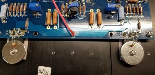
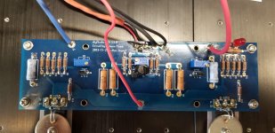
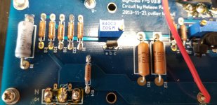
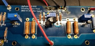
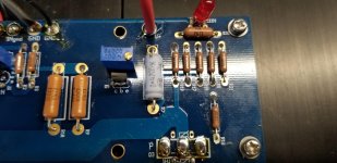
Next carefully check the amplifier boards. Check that you have the Q1, Q2, Q5, and Q6 in the correct positions and oriented correctly. It may be hard to check Q1 and Q2 since that are face to face, but if you carefully separate them by bending the leads a bit, you probably will be able to see the markings.
I confirmed that Q1, 2, 5, 6 are in the correct positions on the right channel.
Check the resistance across resistors R5 and R6 again (indicates correct potentiometers P1 and P2 setting). The resistance should be low, near or at zero.
I measured R5 @ .839 ohms and R6 @ .841 ohms
I added photos in case I'm missing something.
Thanks for the help.
Attachments
Trouble Shooting
Hey Chiptech,
Just my two cents. Double check to make sure none of your wiring protrudes through the pcb and touches the heatsinks.
Zen Mod made a comment in one of the F5 threads about the "thermistors" touching the metal washers. If the protective covering has a scratch, current flows to the heatsinks. Maybe remove the large washers and make sure the thermistors are only touching the plastic case of the mosfet.
As my Dad said many years ago, "It ain't nothing but an old piece of wood. Don't let it outsmart you.
Keep at it. I am listening to "Bachman Turner Overdrive" on my F5 as I type this. You will be very pleased with all of your hard work.
Ty
- Home
- Amplifiers
- Pass Labs
- An illustrated guide to building an F5