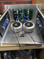
progress so far. Any harm in the V+, V-, and ground wires staying at the top connector of PSU board and route around to the amp boards? I realized I do want to remove the connectors and solder the wires directly to the board. Not seen are two CL-60 between the psu board ground and chassis.
Attachments
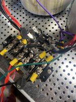
Just wired up everything between the power switch and transformers. 4 CL-60s are used here and 2 safety caps.
1 across each neutral, 1 across each live and the safety caps across each. Two wires come off the terminal block to connect to the inlet.
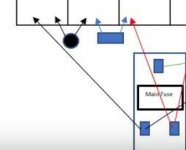
is there any harm in wiring the CL-60 right before the fuse (shown below)? I have one main fuse at the block then one for each transformer.
1 across each neutral, 1 across each live and the safety caps across each. Two wires come off the terminal block to connect to the inlet.
is there any harm in wiring the CL-60 right before the fuse (shown below)? I have one main fuse at the block then one for each transformer.
Attachments

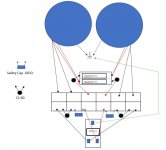
You have your safety caps in series with your in-rush thermistors. The cap goes straight across hot and neutral on the mains. Fix that and the fact that you have a 10 ohm thermistor that will immediately go to <10ohm right across your mains effectively shorting mains (added pic). Also assuming your representation is for a terminal block where each vertical pair shares continuity.
The purple (for Antek) shields go to chassis / safety earth just like you have them. Not sure where you show a wire running to the center of the transformer bolt, but yeah... if so... remove that if it goes to ground.
Move forward from there. Still potentially a few more errors, but one step at a time. Lots and lots of great pics with each transformer fused in the threads for reference.
Attachments
Last edited:
I think 6l6 was referring to my picture of the amp but that wire wasn’t connected to anything. It was just pushed aside and appeared to be attached to the bolt. It will go to chassis ground. Yes, the drawing is of a terminal block where vertical pairs share continuity.
I think my biggest issue is finding how to incorporate separate fuses for each transformer after the block everything.
do the CL-60 need to go across a transformers 2 red primary wires? Or can it go between a twisted pair of primary red wires and the wire from iec inlet?
I think my biggest issue is finding how to incorporate separate fuses for each transformer after the block everything.
do the CL-60 need to go across a transformers 2 red primary wires? Or can it go between a twisted pair of primary red wires and the wire from iec inlet?
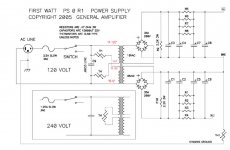
CL-60 for reduction of turn-on current surge should be wired in series with each separate transformer primary. If the primaries are in series for 220V then only one thermistor is needed.
AC fuse should always be on the live line between the input into the case and the power switch.
AC fuse should always be on the live line between the input into the case and the power switch.
Attachments
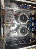
Sorry for all the troubles. I’ve built quite a few of these but never tried dual mono so trying to wrap my brain around it.
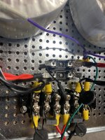
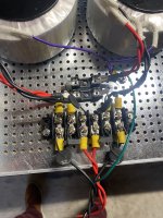
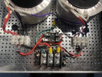
I simplified it and did two separate 4 piece blocks just like 6l6’s build guides.
I didn’t have any spare ceramic terminals so I will use plastic and replace later.
the middle bottom 3 post terminal is for safety, live, and neutral.
I simplified it and did two separate 4 piece blocks just like 6l6’s build guides.
I didn’t have any spare ceramic terminals so I will use plastic and replace later.
the middle bottom 3 post terminal is for safety, live, and neutral.
Attachments
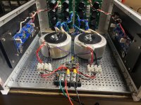
Good news. Power supplies passed the dim bulb test.
After I wired the boards and both passed the test.
Next to cut out my back plate and mount everythint and set bias and dc offset.
for a dual mono with 25V on the rails, what should I set the bias at? Or do I just follow the recommendation on the guide?
After I wired the boards and both passed the test.
Next to cut out my back plate and mount everythint and set bias and dc offset.
for a dual mono with 25V on the rails, what should I set the bias at? Or do I just follow the recommendation on the guide?
Attachments
Amp biased fine and sound comes through speakers.
Only problem I had is I accidentally adjusted P3 and now both are out of whack.
I had the trimmer centered before installing.
Any recommendation of how to center them by measuring with DMM or should I just count the turns to get them equal?
Only problem I had is I accidentally adjusted P3 and now both are out of whack.
I had the trimmer centered before installing.
Any recommendation of how to center them by measuring with DMM or should I just count the turns to get them equal?
Attachments
- Home
- Amplifiers
- Pass Labs
- An illustrated guide to building an F5