I have just built my first Pass Amplifier.
And it is realy all as good as you have been told on those forums.
Yes I know there is loads of treads on this build.
But I rather start my own than barge in on somebody else, besides time to turn a new leaf and get on.
And it is realy all as good as you have been told on those forums.
Yes I know there is loads of treads on this build.
But I rather start my own than barge in on somebody else, besides time to turn a new leaf and get on.
Attachments
You may ask yourself.
(talking heads - once in a lifetime - live 80 rome hq)
Just goggle it.
Why a new tread?
Simple my F5 is making sweet music but a few issues to solve and possibly make it beter.
It is newer going to be good looking as same Flat Pack stuff you buy from IKEA but I have made it.
Recap
26 V rails
Currently biased at 3.5 A
I have a doggy 1000VA transformer
230 V primary
0 20 24 V
0 20 24 V secondary
I am using the 20 V taps at present
150 mU capacitors banks in CRCLC
I have split the last 50 mU between the two channels for total 200 mU
I am using 10mU 63 V capacitors beter quality at 2 times the price on their way
I am building this in the UK and trying to source most of the components from around here supporting the local economy and at the same time get screwed.
Thus the doggy transformer
As it makes a fair bit of mechanical noise (not Much but enough to spoil things)
This is in hand and will be either sorted or manufacturer name and shamed.
I am making my own PCB with a DIY light box £200 + to buy one is rape.
(If you need help on cooking your own just PM)
I have room for 3 mosfets on each branch and I am not using the current limiter.
But I have used the NTE7100 for speaker protection.
Whit Amplimo relays
This worked well in a couple of occasions so I still have
The speakers soon to be replaced are 4 Homs nominal.
At present I have 2 Toshibas on each rail biased at 1.75 A
Next build 1 Toshiba at 2 A and then Fairchild and Cascode and balanced and ….
Now just one reason why I think this tread may be a help to others.
R1 and R2 are 10R 2W Holco and the R5 / R8 combinations are also made up with 3-150R Homs 2W Holco
I like the sound of those resistors and for the money I think that is difficult to find beter MF series 2W 15 ppm.
The thing is 2W is plenty they run cool even after 5 6 hours.
If you need same and are in the UK PM
Another thing I am looking at is the value of R3 R4 I am using 1K with the Toshibas and probably can go down even more the advantage is less current trough the pots so more reliability and easier to adjust as more turns
I am using Futabas MCP74 for source resistors the 0.47 R spec values worked quite well but with 720 mV drops across them was a bit to hot so I am using 0.22R instead.
www.diyaudio.com/forums/swap-meet/182480-holco-mfr-15ppm-2w-sale.html
Not much progress with the build today
Every time I stop to play a couple of tracks I get carried away and end up pulling out quite a few albums.
The Mule has been playing now for a couple of weeks sound seems to have mellowed down a bit maybe just me getting use to it.
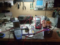
Time to start another round of mosfet testing
While I was doing this the firs time I have noticed that VGS changes quite a bit with the temperature.
I have made myself a little test rig and can get temperature stable with in + - 1 C
A simple 317 a spare mosfet and one of the 4K7 R thermistors + a few bits that may be in anybody bits stash.
May be handy as fan controller for same.
http://www.diyaudio.com/forums/swap-meet/182480-holco-mfr-15ppm-2w-sale.html
Every time I stop to play a couple of tracks I get carried away and end up pulling out quite a few albums.
The Mule has been playing now for a couple of weeks sound seems to have mellowed down a bit maybe just me getting use to it.
Time to start another round of mosfet testing
While I was doing this the firs time I have noticed that VGS changes quite a bit with the temperature.
I have made myself a little test rig and can get temperature stable with in + - 1 C
A simple 317 a spare mosfet and one of the 4K7 R thermistors + a few bits that may be in anybody bits stash.
May be handy as fan controller for same.
http://www.diyaudio.com/forums/swap-meet/182480-holco-mfr-15ppm-2w-sale.html
Attachments
interesting, i may send you a message tomorrow. this lower vgs/higher gm at low temp is really quite interesting as an angle to gain better performance, interesting because you mainly see reference to devices needing to warm up to reach proper performance levels, where your results and mine indicate that a major factor in performance is actually considerably better at low temp. makes sense i guess what with super conductors performing at low temps, i wonder if its the same mechanism at work?
i think the fan+controller is very important, as otherwise the heat added by the dut will always impact on the temp of the sink, over and above the temp created by the heating element and without the fan to burn heat off in a controlled manner you will still be relying on environmental conditions, which are not so predictable.
Tanks QSP
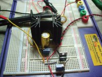
Ditails of the test rig
A cpu heat sink and a piece of copper big pot in the front to set Gate voltagge
I got the thermistor in a small indent right under the Dut to get rid of a bit of time lag.
While I test one Dut the next ones are warming up on the plate noticed this saves time as well
No much chance for me to do any more work today as I have found
a pair of mint Gales Gold Monitors from the secon hand shop for £35.
They sound realy good so got stuck with listening to more records near field.
Attachments
On cooling so I shall read Papa F5 manual one more time as penitence for being out of topic.
Well I was thinking at one stage that down there you all have Air Con
All you have to do is tee off the cold pipe and run that on a coil of copper pipe wound on the heat sinks.
Not kiding you realy looked in to it even found that Halfrouds sels a botle of proper gass to refill the car air con
Well I was thinking at one stage that down there you all have Air Con
All you have to do is tee off the cold pipe and run that on a coil of copper pipe wound on the heat sinks.
Not kiding you realy looked in to it even found that Halfrouds sels a botle of proper gass to refill the car air con

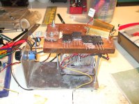
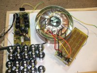
Ok long time since I have been here and time for update.
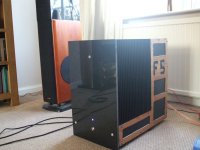
The Mule is no more I have been so impressed by the sound that it is time to invest same time and build something to make Papa proud.
So recap
http://www.diyaudio.com/forums/swap-meet/182480-holco-mfr-15ppm-2w-sale.html
The Mule is no more I have been so impressed by the sound that it is time to invest same time and build something to make Papa proud.
So recap
http://www.diyaudio.com/forums/swap-meet/182480-holco-mfr-15ppm-2w-sale.html
Attachments
-
 Old F5 no more 001.jpg601 KB · Views: 569
 -
 Old F5 no more 003.jpg611.9 KB · Views: 433
 -
 Old F5 no more 004.jpg619.6 KB · Views: 340
 -
 Old F5 no more 012.jpg631.1 KB · Views: 309
 -
 Old F5 no more 011.jpg614.8 KB · Views: 527
 -
 Old F5 no more 007.jpg623.1 KB · Views: 266
 -
 Old F5 no more 014.jpg603.8 KB · Views: 283
 -
 Old F5 no more 015.jpg604.1 KB · Views: 288
 -
 Old F5 no more 018.jpg612.4 KB · Views: 464
On the previous post a few pictures of the Mule.
I hope that there may be something useful there, as I would like this to be my little way to give something back.
I have seen a few posts complaining about the Hum (mains noise on speakers).
I found this a bit strange, as I did not have any.
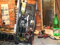
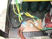
The main thing is using star or bus of star for the earth arrangement.
I did not connect the screen of the Input cable at any other place than the RCA Plugs on the Preamplifier and I was using over 15 Ft of cables from the pre.
The green Yellow cables (UK standard) are the ground
The 4 black ones the grounds of the first 2 capacitor banks.
Only one cable back to the mains and as the Pre has this connection as well that is more than enough to keep the input voltage from floating
http://www.diyaudio.com/forums/swap-meet/182480-holco-mfr-15ppm-2w-sale.html
I hope that there may be something useful there, as I would like this to be my little way to give something back.
I have seen a few posts complaining about the Hum (mains noise on speakers).
I found this a bit strange, as I did not have any.
The main thing is using star or bus of star for the earth arrangement.
I did not connect the screen of the Input cable at any other place than the RCA Plugs on the Preamplifier and I was using over 15 Ft of cables from the pre.
The green Yellow cables (UK standard) are the ground
The 4 black ones the grounds of the first 2 capacitor banks.
Only one cable back to the mains and as the Pre has this connection as well that is more than enough to keep the input voltage from floating
http://www.diyaudio.com/forums/swap-meet/182480-holco-mfr-15ppm-2w-sale.html
Attachments
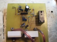
I did not use the current limiters as in Papa SCH and I am not planning to do so
But I had a speaker protection board that did work.
(While I was doing really silly things).
I am using the NTE7100 and Amplimo speaker protection Relays.
Those have 2 set of contacts and designed for this purpose
A tungsten contact closes first then a gold contact
On opening the Gold contact open first followed by the Tungsten
The Tungsten contact take care of the arching that inevitably effect DC contacts
The gold ones are there for beter sound.
I don't have any wish to sell those and if you know a similar or better relay for the job please let me know.
Normal relays are not good especially if they are AC rated, as DC is what you get on the protection circuit when it works
If you find commercial offerings with Ac relays you may have a problem.
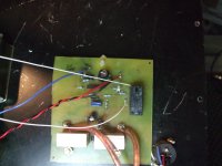
I did not make a drawing of the circuit but went straight for the PCB as in the picture.
I will make a proper drawing and PCB lay out available to all as soon as I can.
http://www.diyaudio.com/forums/swap-meet/182480-holco-mfr-15ppm-2w-sale.html
But I had a speaker protection board that did work.
(While I was doing really silly things).
I am using the NTE7100 and Amplimo speaker protection Relays.
Those have 2 set of contacts and designed for this purpose
A tungsten contact closes first then a gold contact
On opening the Gold contact open first followed by the Tungsten
The Tungsten contact take care of the arching that inevitably effect DC contacts
The gold ones are there for beter sound.
I don't have any wish to sell those and if you know a similar or better relay for the job please let me know.
Normal relays are not good especially if they are AC rated, as DC is what you get on the protection circuit when it works
If you find commercial offerings with Ac relays you may have a problem.
I did not make a drawing of the circuit but went straight for the PCB as in the picture.
I will make a proper drawing and PCB lay out available to all as soon as I can.
http://www.diyaudio.com/forums/swap-meet/182480-holco-mfr-15ppm-2w-sale.html
Attachments
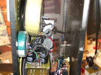
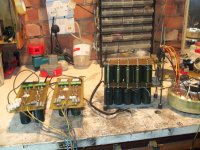
As this was my first build of Papa amp I started up with same rather large transformers
1000 VA giving me the option to build something else eventually
Twin secondary at 0 20 24 V
Imo the mule did sound better with the hi voltage (24 AC) giving me rails at 32 V DC
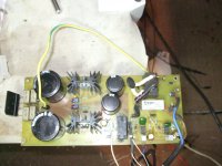
I am using 40 X 10000 uF capacitors in CrCrC configurations with the last bank of capacitors split for the 2 channels.
The inrush current on the thermistors was pretty hi so I had 2 in series
Those are by passed by a relay after a few seconds from power up
Again pretty rough auxiliary supply and timing board
Proper drawing and PCB to follow.
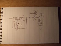
I am using a simple 1 transistor circuit to power up and 555 as delay on timers for power on and soft start.
I would like a more elegant solution using just transistors which would alowd not to use 2 LM317 as 12 V is used just for the 555.
Could you give me any pointer?
http://www.diyaudio.com/forums/swap-meet/182480-holco-mfr-15ppm-2w-sale.html
1000 VA giving me the option to build something else eventually
Twin secondary at 0 20 24 V
Imo the mule did sound better with the hi voltage (24 AC) giving me rails at 32 V DC
I am using 40 X 10000 uF capacitors in CrCrC configurations with the last bank of capacitors split for the 2 channels.
The inrush current on the thermistors was pretty hi so I had 2 in series
Those are by passed by a relay after a few seconds from power up
Again pretty rough auxiliary supply and timing board
Proper drawing and PCB to follow.
I am using a simple 1 transistor circuit to power up and 555 as delay on timers for power on and soft start.
I would like a more elegant solution using just transistors which would alowd not to use 2 LM317 as 12 V is used just for the 555.
Could you give me any pointer?
http://www.diyaudio.com/forums/swap-meet/182480-holco-mfr-15ppm-2w-sale.html
Attachments
Last post for tonight
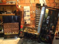
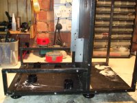
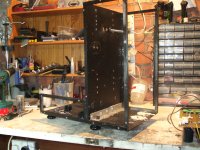
For the Mule I have made myself the enclosure.
Really inexpensive and fit for the purpose
Nice piece of Granite for the front posh and mirror like shining and not IKEA (flat pack furniture that you can proudly say I screw it all together by myself)
I have used 1/2 x 1/2 Aluminium bar as skeleton and really cheap 1mm Aluminium sheet.
The 500X500 Aluminium sheet was about £5.50
The rest of the enclosure was made with play wood 3mm and aluminium mesh.
Super duper ventilation and still not hum
This will all be recycled on the next build.
I will go for a separate PSU case (Hi FI 2000) and 2 towers 150 X 300 X 500 WDH
The sinks are more than big enough to run at 32V 3A and temperature settles at 42 C
So maybe balanced at a bit less bias (I believe balanced gives an equivalent to 4 times the current of the normal equivalent)
Pictures of the old skeleton and probable new PSU lay out
http://www.diyaudio.com/forums/swap-meet/182480-holco-mfr-15ppm-2w-sale.html
Attachments

Actualy chocolate so no crumb whatsoever left got an handy straw to dispose of them.
And tin is andy for lay out as well no moving or dropping heawy trafos...
Whacoo hint..
Work is progressing in the mean time
PCB for new controll circuit getting a coat of tin at the moment then wil have to try out
the new thing just a couple of transistors to do the timing working fine on bread board.
And got my parcell from HI FI 2000 3U X 400 Pesante so the bridges keep cool and the boss told me that black anodised she likes better so once she get involved will be much easier to smugle the lot back in living room...
Please do not tell her that I got 2 of them as is next
As you mention the rattle.
And please help out here with suggestions
Still waiting for other traffo to came back as is gone for same extra varnish to make it quiter.
Apparently they tested the thing and said notting wrong with it and blamed my components.
So the lot got stripped down and I got totaly lost even forgot how to connect the transformer at one point.
No noise change whit wires wrong way around?????
Realy strange in it?
Any way it seems quiter whit slower bridges but one thing puzle me from looking at it and passing a magnet close by it sems that there is quite a bit of extra wire on one particuar spot and the flux is preaty strong there.
This is no good?
When I have asked for the traffos I did say I wanted the best they could make which probably it is (no naming them at moment to give them chance to put things right).
Also quick try to caps with 30 X 10mU was no fun and meter just get out of range
they all seems ok no shorths as all discharging about same rate.
One thing I could not test ESR (not that I am espetting much out of Samwa caps)
but I think I have seen somewhere that if ESR is poor it could cause trafos noise?
And tried DC stopper diode bridge and 2 X12mUback to back (total 4 caps) 6.8V
no change
so help please hum is purely meccanical no noise at all out of speakers till the needle drop on the groove
1)dogy components causing hum even at 3A current (this is 3A in each winding as otherwise F5 will not ofset to zero DC is this right?) trafo 1000 VA so should be good for 20A
2)poor trafo construction or trafo builder do not understand "I am making super duper class A amplifier and would like the best you can make" (drop suplier name somewhere so no more maney wasting from diy brothers)
3) I am to fussy and litle mech noise is just normal any traffo would do that.
1000VA humming at 3A do not think so.
Get same serious money to get reputable brand Traffo which may make same noise becose I am to fussy or spend a bit more and get reputable brand to make a R core?
So the more I think about it the more lost I get help please.
And tin is andy for lay out as well no moving or dropping heawy trafos...
Whacoo hint..
Work is progressing in the mean time
PCB for new controll circuit getting a coat of tin at the moment then wil have to try out
the new thing just a couple of transistors to do the timing working fine on bread board.
And got my parcell from HI FI 2000 3U X 400 Pesante so the bridges keep cool and the boss told me that black anodised she likes better so once she get involved will be much easier to smugle the lot back in living room...
Please do not tell her that I got 2 of them as
is next As you mention the rattle.
And please help out here with suggestions
Still waiting for other traffo to came back as is gone for same extra varnish to make it quiter.
Apparently they tested the thing and said notting wrong with it and blamed my components.
So the lot got stripped down and I got totaly lost even forgot how to connect the transformer at one point.
No noise change whit wires wrong way around?????
Realy strange in it?
Any way it seems quiter whit slower bridges but one thing puzle me from looking at it and passing a magnet close by it sems that there is quite a bit of extra wire on one particuar spot and the flux is preaty strong there.
This is no good?
When I have asked for the traffos I did say I wanted the best they could make which probably it is (no naming them at moment to give them chance to put things right).
Also quick try to caps with 30 X 10mU was no fun and meter just get out of range
they all seems ok no shorths as all discharging about same rate.
One thing I could not test ESR (not that I am espetting much out of Samwa caps)
but I think I have seen somewhere that if ESR is poor it could cause trafos noise?
And tried DC stopper diode bridge and 2 X12mUback to back (total 4 caps) 6.8V
no change
so help please hum is purely meccanical no noise at all out of speakers till the needle drop on the groove
1)dogy components causing hum even at 3A current (this is 3A in each winding as otherwise F5 will not ofset to zero DC is this right?) trafo 1000 VA so should be good for 20A
2)poor trafo construction or trafo builder do not understand "I am making super duper class A amplifier and would like the best you can make" (drop suplier name somewhere so no more maney wasting from diy brothers)
3) I am to fussy and litle mech noise is just normal any traffo would do that.
1000VA humming at 3A do not think so.
Get same serious money to get reputable brand Traffo which may make same noise becose I am to fussy or spend a bit more and get reputable brand to make a R core?
So the more I think about it the more lost I get help please.
........
2)poor trafo construction or trafo builder do not understand "I am making super duper class A amplifier and would like the best you can make" (drop suplier name somewhere so no more maney wasting from diy brothers)
.....
exactly
when I tell to my supplier - " Iwanna300VAdonutwithstaticshield2x18Vacindependentnotcentretapped36VacanditwillworkinclassAampwith100VAconstantjuice" , he answer : "yeahcorewillbedoublebakednextsizeandwirewillbesomewhatthickerbutI'llchargejust10%morethanforusuall300VAdonutmadeforhalogenbl/i/o/nding"
simple , isn't it ?
at least 'till first time he forget to pass that info to winder

btw. - all what proper xformer can and must emanate is feel of scare and respect , in area 5 times greater than his own dims .
buzz isn't included , just because clever xformers know that old farts are usually deaf , and they must be scared , too ........
so - just matter of efficiency - don't waste power on buzz , so you can scare them more

papadilipy almost sorted ; issues with pcb vendor too .
Pumpie dayz soon .....

you could try these tx vibration washers
which doesnt stop the vibration, but they work reasonably well to damp it. probably you can get something else similar, or design your case with some form of damping washer on the mounting for the tx.
obviously its better if they just dont vibrate, i have found sumR toroids i have dont.
i do wonder what the tin is for though, its probably amplifying the noise due to resonance and it certainly wont be doing anything at all to shield the transformer
An externally hosted image should be here but it was not working when we last tested it.
which doesnt stop the vibration, but they work reasonably well to damp it. probably you can get something else similar, or design your case with some form of damping washer on the mounting for the tx.
obviously its better if they just dont vibrate, i have found sumR toroids i have dont.
i do wonder what the tin is for though, its probably amplifying the noise due to resonance and it certainly wont be doing anything at all to shield the transformer
Tanks Qusp and Zen
1) Tin is useful for setting up things
2) And same function as enclosed tinned trafos for free.
3) And it looks pretty and excuse getting more Jummies.
Load of washer’s there thing is Zen hit the nail I think
As this was more an experiment (My first Papa Amp) Trafos where more Than half price than SumR + got 2 taps at 20 and 24 V to play with so SumR will be out.
They will be handy for next experiment and bench supply + got Wakoo idea to use same Thermally conductive potting silicone if the one due back if still noisy after moods.
Maybe and more difficult to judge is option 3 me being too fussy.
Still one learn by mistakes and once I have decided how hard I need to push the mosfets
(Got choice between 26 and 32 V dc at present) Proper traffo it will be F5 to good and quiet to spoil things for the sake of a few quids.
Questions
Any one in UK able to build a traffo to compete with SumR?
Race core will be beter but who’s make them?
http://www.diyaudio.com/forums/swap-meet/182480-holco-mfr-15ppm-2w-sale.html
PS I will waith for it sorry to be nag
1) Tin is useful for setting up things
2) And same function as enclosed tinned trafos for free.
3) And it looks pretty and excuse getting more Jummies.
Load of washer’s there thing is Zen hit the nail I think
As this was more an experiment (My first Papa Amp) Trafos where more Than half price than SumR + got 2 taps at 20 and 24 V to play with so SumR will be out.
They will be handy for next experiment and bench supply + got Wakoo idea to use same Thermally conductive potting silicone if the one due back if still noisy after moods.
Maybe and more difficult to judge is option 3 me being too fussy.
Still one learn by mistakes and once I have decided how hard I need to push the mosfets
(Got choice between 26 and 32 V dc at present) Proper traffo it will be F5 to good and quiet to spoil things for the sake of a few quids.
Questions
Any one in UK able to build a traffo to compete with SumR?
Race core will be beter but who’s make them?
http://www.diyaudio.com/forums/swap-meet/182480-holco-mfr-15ppm-2w-sale.html
PS
I will waith for it sorry to be nag
Last edited:
- Status
- This old topic is closed. If you want to reopen this topic, contact a moderator using the "Report Post" button.
- Home
- Amplifiers
- Pass Labs
- My F5