Hi Cambe
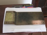
Shuld be ok and probably will give you less time lag than the 13 mm plate I have.
This may be a bonus
Just keep mosfets and the Thermistor as close as you can maybe clamp the thermistor just under the center of the Mosfet
A green kitchen scourer and same elbow grease shuld be enoug to get it shainy.
The only place you need good thermal contact is under the mosfet and the area under it
where you clamp the CPU cooler.
Turbo is out and I have let things go a bit.
MY F5 sound much beter than same stuff I would have got from the shop.
Silly me I was winding up people on the main F5 tread (totaly out of caracter I must say)
Sems like altrought I got cascoded duble J fets at imput no current limiting circuits dubles mosfets and 24 V trafos this does not qualify as being a Turbo already.
Any way Any question you have and any help I can give will be done on this tread as I do not want to hi jack the rest and bore the general population.
You got 2 buttons to press: subscribe to this tread and Ingnore Memeber.
I do not see myself going for version Turbo V3 I am working on decent pre and Phono stage but the bolts are there for a Xbalanced version eventualy
MY F5 sound much beter than same stuff I would have got from the shop.
Silly me I was winding up people on the main F5 tread (totaly out of caracter I must say)
Sems like altrought I got cascoded duble J fets at imput no current limiting circuits dubles mosfets and 24 V trafos this does not qualify as being a Turbo already
.Any way Any question you have and any help I can give will be done on this tread as I do not want to hi jack the rest and bore the general population.
You got 2 buttons to press: subscribe to this tread and Ingnore Memeber.
I do not see myself going for version Turbo V3 I am working on decent pre and Phono stage but the bolts are there for a Xbalanced version eventualy
Tank you ra7
Just dont post that on the main treads or quite a few get P off.
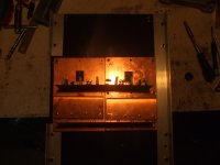
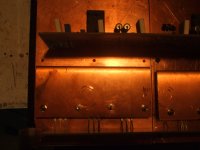
Alluminium bar is fine the Kerafoll love loads of pressure.
And the mosfett for the Turbo love Kerafoll.
Here is better detail.
Yes was going for triple at one stage but I only need 12 V RMS to play loud so decided agains the waste of electricity.
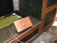
The 3 rd picture is a blok of copper for the star ground it shows how the M4 bolts head is sunk on the heath spreaders so they do not turn.
Just dont post that on the main treads or quite a few get P off.
Alluminium bar is fine the Kerafoll love loads of pressure.
And the mosfett for the Turbo love Kerafoll.
Here is better detail.
Yes was going for triple at one stage but I only need 12 V RMS to play loud so decided agains the waste of electricity.
The 3 rd picture is a blok of copper for the star ground it shows how the M4 bolts head is sunk on the heath spreaders so they do not turn.
Attachments
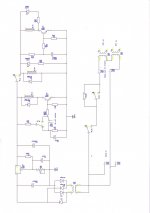
F5 control board
I am using an auxiliary supply to power up My F5
Mains cams in after a EMF filter and DC protection circuit
The first transformer and LM317 give me regulated 24 V
A one transistor on off relay give me power on off for the main circuit with a normaly open push button
The main transformer is a 1000 VA dual output with taps at 20 and 24 V
is connected to the mains when RL 2 closes
As I am using 200 mU of capacitance the start up current was to much for one CL60
So I am using 2 in series
A further one transistor timer switches on a third relay that By pass the CL60
Thermistors once the capacitors are charged that otherwise will get prety hot
Attachments
Last edited:
- Status
- This old topic is closed. If you want to reopen this topic, contact a moderator using the "Report Post" button.
- Home
- Amplifiers
- Pass Labs
- My F5