Board from top looks preaty neat
So supose no bubus on botom.
You may have caused same dammage already so beter cek the mosfet best
way by triing the VGS matching.
Same for the J fets
Burn look preaty bad on the 47? gate resistor so quite a bit of current/voltagge gone troug.
Did you use the light bulb?
PS I had a Jfet gone bad and with litle meter it mesured ok toke a couple of hours of major head bashing to finaly decide to put in a fresh one.
Once done problem solved.
Actually no, I didn't test my supply voltages. QUOTE]
'Just always a good idea to test, as you go, wherever you can. Testing the power supply, before you hook up the amps is "insurance". In case the power supply has problems, you can catch them before you hook up the amp PCBs and damage them.
Having said that, unclear is the power supply is the source of your problems. Are you having identical problems with both Jim's Audio boards (burning the same resistors)?
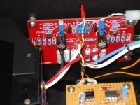
I've looked at your pics, and compared them to my Jim's boards, and you seem to have the caps, semiconductors and trimpots installed OK (as long as they were set to minimal resistance at the start). Difficult for me to confirm your resistor values, from your pics.
I'll get into the schematic, and see if I can get some ideas.
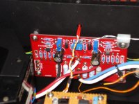
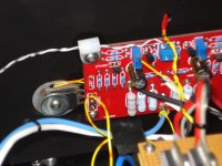
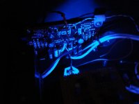
In the meanwhile, here are some pics of my Jim's boards. I had no problems on start-up and in continued use. The first two pics are the left channel PCB, while the third pic is the right channel PCB. I've included the fourth pic, just because when the PCBs are illuminated by the blue LEDs inside the case and viewed through the bronze plexiglass top panel, they just look so darned sexy(!).
Don't be frustrated--the final F5 is well, well worth any agnst you may now be going through.....!
Ken
Attachments
i dont know how to test any MOSFETs??
i didnt end up using the light bulb, i have a feeling i would be able to catch something if i did end up using the light bulb.
and i've double checked everything that i installed, and it all looks okay, from where i sit. but clearly something is wrong, otherwise i would be enjoying my F5 instead of trying to figure out whats wrong!
across R3 and R4 i dont have quite zero, roughly 1.3? but i dont imagine that makes a whole lot of difference. i ran into an interesting reading though, but i'm gonna replace that 47, and see if i found a fluke, or if the 47 has something to do with what i discovered.
Gate resistor is there to suply (depending on which flawor mosfet) a couple of volts to the gate.
Current there shuld be realy low just what the J fets can cope with.
From the dammage done to it same preaty large current went troug there.
Sorry cant help you more I am still preaty green but IMO Itsmee on post 3 got it.
Maybe there are beter ways but have a look at Fig 1 on practical Mosfet testing for audio article Simplified Test Setup that may hel with testing
So i looked at my PS, unloaded, my voltages are 35.4V and -35.3V.
And i let it run for several hours, and continued to check it, and kept getting the same readings, no excessive heating, or any discoloring of the resistors in the circuit. seemingly functioning fine.
While waiting on what to do with the first channel, i tried getting the other one running, and ran into more issues. My offset is roughly -27V, and adjusting the pots is making no difference. While trying to get either to move, the voltage across R11 was .5mV, but R12 was 434mV. I just dont understand the damage?? and while trying to move my offset, R5, R6, R7, and R8 began to brown, with the scent of hot electronics.
I checked to make sure that the resistances across R4 and R3 move as well, R3 moves from almost 0 all the way up to about 2k while R4 only moves from 0 to 60.
i hope this information helps everyone. and just to clarify, this is on the second channel! not the first, that burnt the 47
Last edited:

CrazyC...... If your intent is to build a "bone stock" F5, best to stick to the published Pass schematic (and Pass narrative) values. That would be rail voltages of +24 and -24 volts, with about 6 amp continuous rating, and 10 amp peak surge.
That means, in the standard CRC configuration, transfo secondary voltages of 18 VAC (dual secondaries), with about 400 VA transfo rating.
Can't say if your current power supply caused your current (no pun intended) problem, but best to go for +/- 24 VDC rails, if you are building the stock F5.
That means, in the standard CRC configuration, transfo secondary voltages of 18 VAC (dual secondaries), with about 400 VA transfo rating.
Can't say if your current power supply caused your current (no pun intended) problem, but best to go for +/- 24 VDC rails, if you are building the stock F5.
hmm, whats the value of this Capacitors on this red board ? 220/35 or something diferent .. i see ther 47/50 ...
what should be best value and what kind of cap ?
The caps on the red Jim's Audio PCBs are 47 mfd, 50 vdc. They are non-critical, and are in fact optional in the design. The Pass design does not use them.
The caps on the red Jim's Audio PCBs are 47 mfd, 50 vdc. They are non-critical, and are in fact optional in the design. The Pass design does not use them.
I presume that they tie to ground, otherwise oscillation is a real possibility.
If in doubt, try taking them out.
More poetry:
When Q4 goes
R14 blows

I presume that they tie to ground, otherwise oscillation is a real possibility.
If in doubt, try taking them out.
More poetry:
When Q4 goes
R14 blows
so if you dont mind me asking, if Q4 goes out, do i just have current flowing strait through it to R14? is that whats happening?
Well, i'm digging this really old thread back up, because i've found myself with a lot of time at home, and i need something to do. so finishing this amp, then having a nice stereo to utilize is my goal here! i ended up ordering a transistor, and a transformer.
After a lot of thinking, i'm wondering if the voltage being to high from the PS is what caused the transistor to fail? either way, i'll be replacing all the components, and starting it back up to get myself moving
After a lot of thinking, i'm wondering if the voltage being to high from the PS is what caused the transistor to fail? either way, i'll be replacing all the components, and starting it back up to get myself moving
It's a simple amplifier, and there are only 4 transistors in it.
The stock unit has +/-23V supplies.
If you have fake input JFETs, that could be the source of some trouble -
you might want to measure the Idss of those. There's plenty of tutorials
around about doing that.
If you can set the pots at 0 ohm, then you should be able to fire it up
with no current draw. Use a multimeter to measure the voltage across
the Source resistors of the Mosfets.

- Status
- This old topic is closed. If you want to reopen this topic, contact a moderator using the "Report Post" button.
- Home
- Amplifiers
- Pass Labs
- new f5 bias problem