The MAGMA is a new front end for a BA-2, F4, or even a slightly
modified Zen-5 amp. It was concieved as a new front end for
the BA-2 that used magnetics to step up the input voltage and was
therefore named MAG-BA. Realizing that it could also be used on
the F4 or Zen-5, the BA part no longer fit. Wanting to stay with
the Burning Amp theme, it is named MAGMA.
The MAGMA is similar in concept (I have no idea about sound) to
the M2, in that:
* it uses a high performance transformer to magnetically step up
input voltage
* aside for degenerative source resistors, it uses no feedback
* it uses a complementary OPS architecture
* as designed, it is fully class A
* as designed, it outputs about 25 watts RMS
* single ended input
* using differential input, pairs of amps should be able to be
bridged together for higher wattage
and so on...
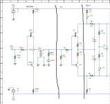
The simplified amplifier architecture is a 2 stage design using a
signal step up transformer followed by a current amplification
section. The complete design uses JFET impedance matching buffers
around the step up tranformer to help linearize the circuit. As
seen in the schematic, input voltage is fed to an impedance matching
buffer that drives the voltage step up transformer, which drives
another impedance matching buffer, which drives the current gain
stage.
The BA-2 can be used as the current gain stage (OPS). Simply
replace the original IPS/VAS of the BA-2 with the buffer/xfmr/buffer
of the MAGMA.
The output section of the F4 and BA-2 are almost identical.
Obvious differences include the DC offset adjustments on opposite
rails, slightly different component values, and possibly a
different number of MOSFETs. Note the inputs to the OPS are
slightly different. The BA-2 also has a facility to provide
feedback, which this design does not use.
As the OPS of the BA-2 and the F4 are the same basic design, and
as the F4 already has a buffer on its front end, the input buffer
of the F4 can be used (without modification) as the second buffer
of the MAGMA. So the new circuitry consists of an input buffer
followed by the transformer (and associated RC network) prefixed
to the normal F4 circuit. Danged ol' easy! 🙂
The vertical lines on the schematic try to indicate the MAGMA/F4/BA-2
sections.
As the MAGMA using the F4 boards from the DIY Store is an easier
build than the BA-2, and as I don't need the extra output devices of
the BA-2, I built the MAGMA prefixed to the F4. I will leave it to the
more industrious types to use the BA-2.
Parts:
The resistors are 1/4 W with values noted on the schematic
The POT P301 is 20 ohms, 1/4 W.
JFETS
Q1 and Q301 are 2SK170BL (N-Channel)
Q2 and Q302 are 2SJ74BL (P-Channel)
Jensen Transformer JT-13K7-A
Cap C301 1300pF, 35V
Construction Notes:
Before installing P301, center the resistance so that it is about
10 ohms between the center and outside pins.
I apologize for the symbol my spice program uses for the P-Channel
JFET. The Drain pin of the P-Channel JFET is towards the negative
rail, and the Source pin is towards the POT.
I run the JFET devices (Q301, Q302) a little hotter than Nelson did
in the F4. You can reduce the current to these devices by using
higher values for R303 and R304 (Nelson uses 1K in the F4). Or
you can leave them where I have them and optionally use little heat
sink tops.
For C301, if you cannot find a 1300pF cap, you can replace it
with a 1500pF cap. I bought a bunch of 1200pF polystyrene caps
and measured one at 1270pF, so I used it. If you can replace
R2 with a 39.2K resistor, the 1500pF value for C301 is just
right.
Initial Turn-on and Adjustments:
Of course, follow Nelson's instructions in the BA-2 paper. In
addition, with no input, measure the voltage between the input
of the signal transformer to ground. Adjust P301 to zero this
value.
do
{
Adjust P301
Adjust bias
Adjust DC offset
Wait a while
} until settings and heat sink temperature are stable
Some measured specs of my prototype into an 8 ohm load:
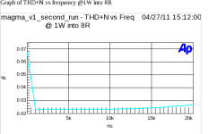
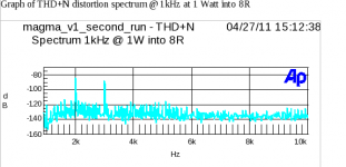
Distortion @ 1 watt @ 1KHz ...... 0.025%
Input Impedance ........................... 100 Kohm
Gain ................................................ 4.485 or 13.03 dB
Input Sensitivity ............................ 633 mV = 1 W, 3.436 V = 29 W
Output power 8 ohms ................. 29 W RMS @ 0.3% THD, 1KHz
.......................................................... 25 W RMS @ < 0.2% THD, 1KHz
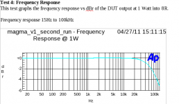
Frequency response ................... +0, - 0.1 dB from 20 Hz to 20 KHz
.......................................................... -3dB around 70KHz
I'll try to post some graphs in a bit...
Sound:
As of this posting, I have only built one channel. So I offer
this only as a rough critique. I think this sounds much like
my DIY F5 (like a complementary amp), except with a little more
"curves" and less "angles". It may be a little softer on the
entire spectrum, but it is hard for me to tell without a sterio
pair. But I'm working on that...
I would like to thank Nelson for permission to post this design.
I would like to thank Nelson and all of the others in this
group for the support they have given me.
Robert Fournerat
modified Zen-5 amp. It was concieved as a new front end for
the BA-2 that used magnetics to step up the input voltage and was
therefore named MAG-BA. Realizing that it could also be used on
the F4 or Zen-5, the BA part no longer fit. Wanting to stay with
the Burning Amp theme, it is named MAGMA.
The MAGMA is similar in concept (I have no idea about sound) to
the M2, in that:
* it uses a high performance transformer to magnetically step up
input voltage
* aside for degenerative source resistors, it uses no feedback
* it uses a complementary OPS architecture
* as designed, it is fully class A
* as designed, it outputs about 25 watts RMS
* single ended input
* using differential input, pairs of amps should be able to be
bridged together for higher wattage
and so on...
The simplified amplifier architecture is a 2 stage design using a
signal step up transformer followed by a current amplification
section. The complete design uses JFET impedance matching buffers
around the step up tranformer to help linearize the circuit. As
seen in the schematic, input voltage is fed to an impedance matching
buffer that drives the voltage step up transformer, which drives
another impedance matching buffer, which drives the current gain
stage.
The BA-2 can be used as the current gain stage (OPS). Simply
replace the original IPS/VAS of the BA-2 with the buffer/xfmr/buffer
of the MAGMA.
The output section of the F4 and BA-2 are almost identical.
Obvious differences include the DC offset adjustments on opposite
rails, slightly different component values, and possibly a
different number of MOSFETs. Note the inputs to the OPS are
slightly different. The BA-2 also has a facility to provide
feedback, which this design does not use.
As the OPS of the BA-2 and the F4 are the same basic design, and
as the F4 already has a buffer on its front end, the input buffer
of the F4 can be used (without modification) as the second buffer
of the MAGMA. So the new circuitry consists of an input buffer
followed by the transformer (and associated RC network) prefixed
to the normal F4 circuit. Danged ol' easy! 🙂
The vertical lines on the schematic try to indicate the MAGMA/F4/BA-2
sections.
As the MAGMA using the F4 boards from the DIY Store is an easier
build than the BA-2, and as I don't need the extra output devices of
the BA-2, I built the MAGMA prefixed to the F4. I will leave it to the
more industrious types to use the BA-2.
Parts:
The resistors are 1/4 W with values noted on the schematic
The POT P301 is 20 ohms, 1/4 W.
JFETS
Q1 and Q301 are 2SK170BL (N-Channel)
Q2 and Q302 are 2SJ74BL (P-Channel)
Jensen Transformer JT-13K7-A
Cap C301 1300pF, 35V
Construction Notes:
Before installing P301, center the resistance so that it is about
10 ohms between the center and outside pins.
I apologize for the symbol my spice program uses for the P-Channel
JFET. The Drain pin of the P-Channel JFET is towards the negative
rail, and the Source pin is towards the POT.
I run the JFET devices (Q301, Q302) a little hotter than Nelson did
in the F4. You can reduce the current to these devices by using
higher values for R303 and R304 (Nelson uses 1K in the F4). Or
you can leave them where I have them and optionally use little heat
sink tops.
For C301, if you cannot find a 1300pF cap, you can replace it
with a 1500pF cap. I bought a bunch of 1200pF polystyrene caps
and measured one at 1270pF, so I used it. If you can replace
R2 with a 39.2K resistor, the 1500pF value for C301 is just
right.
Initial Turn-on and Adjustments:
Of course, follow Nelson's instructions in the BA-2 paper. In
addition, with no input, measure the voltage between the input
of the signal transformer to ground. Adjust P301 to zero this
value.
do
{
Adjust P301
Adjust bias
Adjust DC offset
Wait a while
} until settings and heat sink temperature are stable
Some measured specs of my prototype into an 8 ohm load:
Distortion @ 1 watt @ 1KHz ...... 0.025%
Input Impedance ........................... 100 Kohm
Gain ................................................ 4.485 or 13.03 dB
Input Sensitivity ............................ 633 mV = 1 W, 3.436 V = 29 W
Output power 8 ohms ................. 29 W RMS @ 0.3% THD, 1KHz
.......................................................... 25 W RMS @ < 0.2% THD, 1KHz
Frequency response ................... +0, - 0.1 dB from 20 Hz to 20 KHz
.......................................................... -3dB around 70KHz
I'll try to post some graphs in a bit...
Sound:
As of this posting, I have only built one channel. So I offer
this only as a rough critique. I think this sounds much like
my DIY F5 (like a complementary amp), except with a little more
"curves" and less "angles". It may be a little softer on the
entire spectrum, but it is hard for me to tell without a sterio
pair. But I'm working on that...
I would like to thank Nelson for permission to post this design.
I would like to thank Nelson and all of the others in this
group for the support they have given me.
Robert Fournerat
Attachments
Robert,
I love what you are doing.
Quick question. Have you tried to wire the JT-13K7-A as an auto-former?
If I understand correctly, you get better coupling and slightly higher gain at the expense of higher loading.
Alternately, since the transformer "blocks" DC coupling, would a DCB1 style Shunt regulator have advantages?
Plotting big trouble for moose and squirrel,
Doug
Robert,
I love what you are doing.
Quick question. Have you tried to wire the JT-13K7-A as an auto-former?
If I understand correctly, you get better coupling and slightly higher gain at the expense of higher loading.
Alternately, since the transformer "blocks" DC coupling, would a DCB1 style Shunt regulator have advantages?
Plotting big trouble for moose and squirrel,
Doug
Hi Doug,
Sorry for the slow reply, I've been building that 2nd channel, which I
can now report is done!
I got the JT-13K7-A directly from Jensen Transformer, and they are in a
sealed (I assume Faraday) enclosure. I looked for some autoformers,
and even built a few for experiments. But I could not find or build (for a
reasonable price) any with the performance of the Jensen's. In software
(which is what I do) there is a saying that goes, "Why re-invent the
wheel". I could not build a better wheel (or xfmr), so I used the Jensens.
I'm not familiar with the DCB1 project. I'll have to read more about it.
Robert
You can wire the Jensen as a transformer or as an autoformer.
As an autoformer, I believe you wire red to orange, rather than orange to ground.
I agree that the Jensen is a fine unit.
Thanks for sharing your work.
Doug
As an autoformer, I believe you wire red to orange, rather than orange to ground.
I agree that the Jensen is a fine unit.
Thanks for sharing your work.
Doug
Shewww, I thought you ment to rewire the core! And I wasn't
looking forward to that task. 🙂
That is very interesting news to me. I'll try to check with Jensen
tomorrow. Thanks for the info!!!
Robert
looking forward to that task. 🙂
That is very interesting news to me. I'll try to check with Jensen
tomorrow. Thanks for the info!!!
Robert
I expect you have read this thread?
http://www.diyaudio.com/forums/tubes-valves/150788-transformer-voltage-gain-element.html
http://www.diyaudio.com/forums/tubes-valves/150788-transformer-voltage-gain-element.html
This is an interesting subject. If you want to pursue it, I
suggest that you try as many different samples of transformer
as you can, as they are all different, and there are some
surprises to be had. Also keep in mind that these pieces all
love a low source impedance.
😎
suggest that you try as many different samples of transformer
as you can, as they are all different, and there are some
surprises to be had. Also keep in mind that these pieces all
love a low source impedance.
😎
Well, sounds like audiorob's proposed JFET buffer input would be a good start. Now, a standard step up connection or the autoformer connection?
Hmmm
Hmmm
Per DougL's suggestion, I am researching the 13K7 as a autoformer path.
The 1st line of support people at Jensen are very helpful, but they are not
aware of the 13K7 being able to be wired as an autoformer. They have passed
me to the engineers, and I am waiting for a return phone call.
They also suggested the 110K-C (1:8) and 115K-E (1:10). I know nothing
of these devices, I'm just passing along the information.
The thread flg suggests is on topic and someone even suggested the
same idea of using the F4, although they did not go so far as to provide
a design. Still interesting reading. Thanks flg. In that thread, someone
mentioned the CineMag CMMI-10C, which might be another interesting
choice for step up xfmrs.
The output impedance of the JFET buffer is about 20 ohms. Per the Jensen
folks, the 13K7 was designed for microphones, and so is expecting to be
driven by a source impedance of about 150 ohms. Their standard design
presented a 39.2K load to the xfmr, but the standard design for the F4 is
a 47.5K input impedance. To compensate for the lower source impedance
and higher load impedance, the RC network on the xfmr secondary side
was adjusted to the values I gave in the schematic. I believe the phase
shift is centered such that at 20Hz, the xfmr output lags the input slightly,
and at 20kHz, the output leads the input slightly.
Robert
PASSIVE / ACTIVE preamp
It isn't a new solution.
I builded one because i have some probleme of impedance with my passive preamplifier.
A simple buffer BUF 04 with hight performance and a 7902 Lundall tranformer, two acculators 12 v , 2.4 Ah.
The BUF04 is for the low impedance in enter of the transfo ( 50 ohm )
Gain 14 db
Very very low distorsion arround -130 db
No capacitance in the line
Outpout banlenced or not
And great sound i have difficulties to do a difference with my direct num enter.
I wonder if that front-end with Q301 + Q302 feeding a proper transformer is good idea to convert single ended input into F4 bridged to balanced?
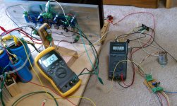
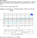
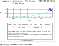
Here are some of the graphs I promised. It might be important to note that the
amp is a work in progress, and has test leads running everywhere. It might also
be noted that some of these tests drive the 13K7 to fairly high levels.
amp is a work in progress, and has test leads running everywhere. It might also
be noted that some of these tests drive the 13K7 to fairly high levels.
Attachments

Hi audiorob,😀
These values look really good, you open an interesting new place to play with....🙂
And I think Dougl is right, to get an autoformer you connect red an orange to get one big winding and the input is between brown and red and the magnified output between brown and yellow....
I learned from Zen Mod if I understood his words right.....
Last edited:
Here are a couple of extra build notes:
First, my magma uses a power supply that I discussed in the F5 thread. The
supply is CLC, then regulated via a 317/337 circuit with bi-polar pass transistors
feeding a final set of caps (similar to the Zen 5 power supply). I tried zener and
TL431 based circuits using mosfet and bi-polar pass transistors. While not
cheap, the 317/337 with bi-polar pass transistors made such a large difference
(in regulation and sonicly) on the F5 that I haven't experimented with much else...
The regulated supply was needed due to the wall power fluctuations where I live.
While I don't know about long term, lately, the wall voltage fluctuations have been
even worse than normal, and the magma is sensitive to this. The DC offset of
the magma will vary if your rail voltage varies from each other. I suspect this is
true of the F4 and BA2, but this is the magma thread. I had to turn down my
rails to 22V (in my case, a little more than 6V losses due to regulation).
The second issue is that I used TIP-33/34C pass transistors in my F5 power
supply design. The F5 draws about 1.3A from each rail. The TIP-33/34C parts
are rated at 10 amps. Right now, I have my magma biased at about 1.5 amps
per channel, per rail. I'm driving 2 channels with a power supply, so I'm
drawing about 3A per rail. Even though the 33/34C's are operating well within
their SOA, I've changed to 35/36C's (rated at 20A), and this has made a very
large difference in bass performance of the amp.
Hopefully, this will have others some time and frustration.
Robert
I was able to speak with an engineer at Jensen Transformers, and asked him
about connecting the 13K7 as an autoformer, per DougL's and Generg's
suggestion. He said it can be done and yeilds a 1:6 winding ratio (and 1V in,
6V out) with very similar specs as connected normally. The transformer core
still saturates at the same input level, but as an autoformer, you get higher
voltage output.
Per the Jensen specs, the transformer is at about 1% THD at 7dBu at 20 Hz.
7dBu is about 2.453Vp. 2.453Vp * 6 = 14.718Vp. Let's just round that to 15Vp.
Or at 30 Hz, the transformer is at about 0.6% THD at 10 dBu. 10dBu is about
3.464Vp. 3.464Vp * 6 = 20.784Vp
If we have 23V rails, minus about 5.5V for bias an losses from the souce
resistors on the output MOSFETs, means we can drive the MOSFETs with
about 17.5Vp of signal before clipping.
(17Vp ^2) / 8 Ohms = 36.125 Wp into 8 Ohms.
Or, with 2.453Vp of input at 20 Hz, we can drive the rest of the circuit to get a
little less than (15Vp ^ 2) / 8 Ohms = 28.125 Wp output into 8 Ohms at about
1% THD. At 30 Hz, we are less than 1% THD before driving the rest of the
circuit to clipping.
That's the theory anyway...
As connecting the transformer as an autoformer is an easy thing to do (or undo),
and it provides a higher step up ratio, I have connected mine as an autoformer.
What I did was to ground the Red wire. Connect the Brown and Yellow wire
together and connect them to the input. Connect the Orange wire to the output.
Nothing else changes.
I've been listening to this for a couple of days now and it I think it is something
extraordinary. I'll try to run some tests and post the specs soon.
Robert
extraordinary .
yes , it is .
moi played much with xformers in last few years ......... some as I/V conversion , some as gain stages
they really shine when you can/must use them differentially ( balanced) , but they're certainly more than good enough in M2-like implementation
yes , it is .
moi played much with xformers in last few years ......... some as I/V conversion , some as gain stages
they really shine when you can/must use them differentially ( balanced) , but they're certainly more than good enough in M2-like implementation
This is an interesting subject. If you want to pursue it, I
suggest that you try as many different samples of transformer
as you can, as they are all different, and there are some
surprises to be had. Also keep in mind that these pieces all
love a low source impedance.
😎
Dear Mr. Pass, autormers from Jensen, Lundahl and so on are fairly expensive.
So it is a bit difficult for most of us to follow your suggestion.....
Do you think you can puplish for instance three favorites of yours......
.....or tell us something about the different pro's of some models?
🙂🙂🙂
- Status
- Not open for further replies.
- Home
- Amplifiers
- Pass Labs
- Introducing the MAGMA front end for BA-2 and F4